Scania DC16 EMS with S6/PDE. Industrial engine. Operator’s manual - part 3


  Index      Scania     Scania DC16 EMS with S6/PDE. Industrial engine. Operator’s manual


Search            copyright infringement  


Content      ..     1      2      3      4      ..


Scania DC16 EMS with S6/PDE. Industrial engine. Operator’s manual - part 3


3. Every 400 hours:

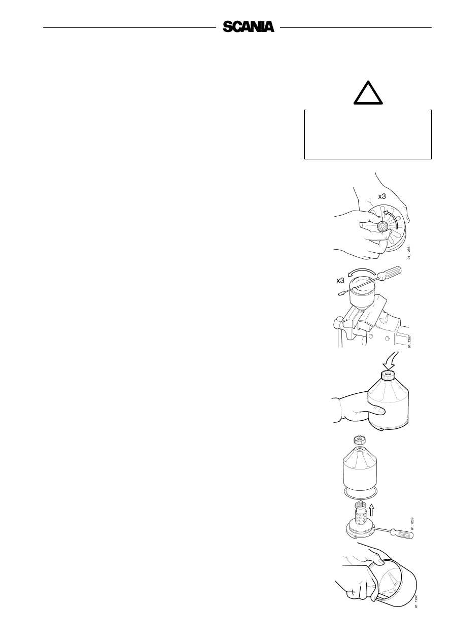
Cleaning the oil filter unit

(in connection with oil change)

01

12

88

Open the cover carefully. The 

oil may be hot.

WARNING

!

- Clean the cover. Unscrew the nut and remove the cover.

- Lift out the rotor and loosen the nut on the rotor cover three turns.

- If the nut is jammed:

Clamp the nut, but never the rotor, in a vice and turn the rotor three 

turns by hand or with a screwdriver.

- Tap the nut lightly with your hand or a plastic hammer, to detach the 

rotor cover from the bottom plate.

- Unscrew the nut and remove the rotor cover.
- Remove the strainer located on the rotor. If the strainer is stuck, you can 

prise its bottom edge carefully until it comes loose from the bottom 

plate.

- Scrape off the deposits from the inside of the rotor cover. If there are no 

deposits, this indicates that the cleaner is not working properly.

- If the deposits are thicker than 20 mm: clean more often.

34

- Wash all parts in diesel.
- Make sure the nozzles on the rotor are not blocked or damaged.
- Check that the bearings are undamaged.

112 

3

14

15 Nm

112 

3

1

3

- Fit the O-ring in the rotor cover. The O-ring must not be damaged.

Renew if necessary.

- Reassemble the rotor.

- Tighten the rotor nut firmly by hand.
- Check that the shaft is not loose. If it is loose, use locking compound 

561 200 and torque tighten to 34 Nm.

- Refit the rotor.
- Check that it rotates easily by rotating it manually.

- Check that the O-ring in the bowl is not damaged.

Renew hardened or damaged O-rings.

- Screw on the cover and tighten the lock nut to 15 Nm.

Tighten the nut carefully so as not to damage the rotor shaft, nut or cover.

Functional inspection

The rotor rotates very fast and should continue to rotate when the engine has 

stopped.

- Stop the engine when it is warm.
- Listen for a whirring sound from the rotor or feel whether the cleaner 

housing is vibrating.

The rotor normally continues spinning for 30-60 seconds after the engine has 

stopped.
If not: dismantle and check.

4. Every 400 hours:

Renewing the oil filter 

(At the same time as an oil change)

- Unscrew the filter cover with a closed tool with hexagon driver, for 

example, socket 587 637, so as not to damage the filter cover.

- Lift out the filter housing lid with filter element. The filter housing will 

drain automatically once the filter has been removed.

- Undo the old filter from the cover by carefully bending it to one side.
- Lubricate a new O-ring with engine oil and place it in the cover.
- Press a new filter element into the snap fastener in the lid.
- Make sure the oil filter drain has emptied the oil from the filter housing.
- Screw on the filter lid with a closed tool with hexagon driver, for 

example, socket 587 637. Tightening torque 25 Nm.

- Start the engine and check for leaks.

Important!

If the deposits in the centrifugal cleaner are more than 

20 mm thick, the oil filter must be renewed more often. The 

same is true for cleaning the centrifugal filter and changing 

the oil.

Renewing the closed crankcase 

ventiltion filter

In the case of engines with closed crankcase ventilation, the filter element and 

prefilter must be renewed at the same time as the main oil filter as described 

below:

- Remove the filter housing cover (1) and remove the filter element (2).
- Remove the prefilter (3) from the filter housing inlet.
- Clean the filter housing and insert a new prefilter.
- Pour approximately 1 dl of oil into the filter housing oil outlet so as to 

ensure that there is sufficient oil in the liquid seal.

- Insert a new filter element and place the cover back on the filter housing.

Use a container to avoid spillage 

when renewing the filter.

Dispose of used filters through 

an authorised waste disposal 

contractor.

Help protect our 

environment!

36

Cooling system

5. Daily:

Checking the coolant level

- Open the expansion tank filler cap and check the coolant level.
- Correct level: (Scania plastic expansion tank)

- Cold engine: Coolant level must be approximately 50 mm below the 

full line.

- Hot engine: Coolant level must be approximately 25 mm below the 

full line.

- Other types of expansion tank according to the instructions of the fitter.
- Top up the coolant as necessary, see point 6.

Note:

When filling large amounts of coolant:

Never pour cold coolant into a hot engine.

This could crack the cylinder block and cylinder head.

Always top up with ready mixed 

coolant.

Open the cover carefully.

Water and steam can spray out.

Important

!

WARNING

!

6. Every 2,400 hours:

Checking the coolant

Coolant should be checked as follows:

a)

Check the appearance of the coolant.

b)

Coolant with glycol only: Check the glycol content.

c)

Coolant containing only Scania Corrosion Inhibitor:

Check the corrosion inhibitor content.

The composition of the coolant is described in more detail under 

"Starting and running".

a)
Checking the appearance of the coolant

- Pour a small amount of coolant in a container, and check that the coolant 

is pure and clear.

- If the coolant is contaminated or cloudy: consider changing the coolant.
- Water for the coolant must be clean and free from contamination.
- Use drinking water with a pH of 6-9.

b)
Checking the glycol content

If there is a danger of freezing, use only glycol as an anti-corrosive in the 

coolant.

- Cooling systems with glycol should contain at least 30% glycol by 

volume to provide acceptable protection against corrosion.

- 30% glycol by volume provides protection against freezing to -16°C. If 

additional protection against freezing is required, see the table on the 

next page to help you calculate how much glycol you need.

We recommend only nitrite-free antifreeze glycols with the following 

supplier designations:

BASF G48 or BASF D542

- Always add glycol if the glycol content drops below 30% by volume. A 

glycol content above 60% by volume will not provide greater protection 

against freezing.

- The table shows the temperature at which ice starts to form. The engine 

will freeze and break at appreciably lower temperatures, see diagram.

- Ice forming in the coolant often causes malfunctioning without any risk 

of damage. The engine should not be subjected to heavy loads when ice 

starts to form.

Note:

The coolant should be changed when the cooling system is 

cleaned: every 4,800 hours or at least every 5 years.

Important!

If a coolant filter is used in the cooling system it must not 

contain an inhibitor.

Coolant composition:

If there is a danger of freezing:

min 30% glycol by volume

max 60% glycol by volume

If there is no danger of freezing:

8-12% by volume

Scania Corrosion Inhibitor

The coolant should be ready 

mixed when it is poured into the 

cooling system.

Never top up with only water or 

only glycol.

Ethylene glycol is highly 

dangerous if imbibed and can 

prove fatal.

Avoid skin contact with glycol.

The recommended glycols must 

not be mixed with glycol 

containing nitrite-based 

corrosion inhibitor.

Risk of build up of sludge and 

reduced cooling capacity.

Important

!

WARNING

!

38

A

A = Area to be avoided. Only for calculating glycol mix.

Coolant freezing temperature, when ice starts to form, for different glycol mixes.

% by volyme glycol

15

20

25

30

35

40

45

50

Cooling system

volume, dm

3

Ice slush starts to 

form at °C

-6

-9

-12 -16 -21 -24 -30 -37

Ethylene glycol

dm

3

 (litres)

5

6

8

9

11

12

14

15

30

6

8

10

12

14

16

18

20

40

8

10

13

15

18

20

23

25

50

9

12

15

18

21

24

27

30

60

11

14

18

21

25

28

32

35

70

12

16

20

24

28

32

36

40

80

14

18

23

27

32

36

41

45

90

15

20

25

30

35

40

45

50

100

17

22

28

33

39

44

50

55

110

18

24

30

36

42

48

54

60

120

20

26

33

39

46

52

59

65

130

21

28

35

42

49

56

63

70

140

23

30

38

45

53

60

68

75

150

24

32

40

48

56

64

72

80

160

26

34

43

51

60

68

77

85

170

27

36

45

54

63

72

81

90

180

29

38

48

57

67

76

86

95

190

30

40

50

60

70

80

90

100

200

Curve A: Ice formation starts (ice slush)
Curve B: Temperature at which there is a risk of damage by freezing

1. Safe range
2. Malfunctions may occur (ice slush)
3. Risk of damage by freezing

Characteristics of glycol at low temperatures:

- Example with 30% glycol by volume
- Ice slush starts to form at -16°C.
- There is risk of malfunctions at -30°C
- No risk of damage by freezing with a minimum 

content of 30% glycol by volume

Antifreeze glycol, % by volume

c)
Checking the corrosion inhibitor

There must always be sufficient corrosion protection (inhibitor) in the coolant 

to protect the cooling system against corrosion.
If there is no danger of freezing, only Scania Corrosion Inhibitor should be 

used in the coolant.
The inhibitor in Scania Corrosion Inhibitoris free of nitrites.
The correct proportion of anti-corrosive is 8-12% by volume. 

- Topping up with 1.0% Scania Corrosion Inhibitor by volume should be 

done after every 2,400 hours of operation.

- Never top up with water alone or corrosion inhibitor alone!

Fluid losses must always be replaced with pre-mixed coolant: 

water + 10% Scania Corrosion Inhibitor by volume.

Note:

The coolant should be changed when the cooling system is 

cleaned: every 4,800 hours or at least every 5 years.

Changing the coolant

1.

Remove the filler cap from the expansion tank.

2.

The coolant is drained at three points:

- 2 drain taps on the lower right side of the block, see illustration
- drain tap on the lower left side of the block (see illustration) and at the 

coolant system’s lowest point outside the engine.

3.

Close the cocks.

4.

Top up with coolant through the expansion tank’s filler hole.
Mix coolant as described on page 37.

If a coolant filter has been fitted 

it must not contain inhibitor.

Mixing with glycol or the use of 

too much corrosion protection 

can lead to build up of sludge 

and reduced cooling capacity.

Corrosion protection is highly 

dangerous if ingested and can 

prove fatal.

Avoid contact with the skin.

Use a container to avoid spills 

when changing the coolant.

Dispose of used coolant through 

an authorised waste disposal 

contractor.

Important

!

Important

!

WARNING

!

Help protect our 

environment!

40

7. Every 4,800 hours:

Cleaning the cooling system

Note:

If necessary, the cooling system should be cleaned more often.

External cleaning

Radiator

- Check that the radiator is not clogged on the air side and that the cooling 

fins are not damaged.

- Carefully scrape the deposit off the radiator’s cooling fins. If necessary, 

a paraffin-based engine cleaner can be used.

- Bent fins can be straightened using a wire brush, for example, and 

exercising care.

The cooling system must never 

be cleaned with caustic soda.

There is a risk of damage to 

aluminium parts.

Important

!

Internal cleaning

Removing oil and grease

- If possible, run the engine until it has reached operating temperature and 

then drain the cooling system.

- Remove the thermostats.
- Fill the system with clean, hot water mixed with liquid dishwasher 

detergent designed for household use.

Concentration 1% (0.1/10 l).

- Run the engine for approximately 20-30 minutes. Do not forget the cab 

heating system (if fitted).

- Drain the cooling system.
- Refill the system with clean hot water and run the engine for about 

20-30 minutes.

- Drain the water from the system.
- Refit the thermostats.
- Top up the system with coolant according to the specification on 

page 37.

Removing deposits

- If possible, run the engine until it has reached operating temperature 

and then drain the cooling system.

- Remove the thermostats.
- Fill the system with clean, hot water mixed with some of the radiator 

cleaning agent available on the market which is based on sulphamic 

acid and contains dispersing agents. Follow the manufacturer’s 

instructions for the concentration and cleaning period.

- Run the engine for the specified time and then drain the cooling system.
- Refill the system with hot water and run the engine for about 

20-30 minutes.

- Drain the water from the system.
- Refit the thermostats.
- Top up the system with coolant according to the specification on 

page 37.

When handling cooling system 

detergent:

read the warning text on the 

containers.

Use a container to avoid spills 

when changing the coolant.

Dispose of used coolant through 

an authorised waste disposal 

contractor.

WARNING

!

Help protect our 

environment!

42

Air cleaner

8. Daily:

Test reading low pressure indicator

If the red indicator bar is entirely visible, change or clean the air cleaner filter 

element, see point 10. This is particularly important if the engine is run at 

high loads and high speed.

9. Every 200 hours:

Cleaning the air cleaner coarse cleaner

1.

Remove the cover from the coarse cleaner (2).

2.

Remove the conical coarse separator. Empty out the particles of dirt and 

clean it.

3.

Fit the coarse cleaner as shown in the figure and screw the cover into 

place.

10. Every 1,200 hours:
Cleaning or renewing the filter element

Note:

Earlier if the low pressure indicator shows red

Dismantling

1.

Remove the side cover from the air cleaner.

2.

Renew or clean the element.

Note:

Cleaning the element always entails a risk of damaging it. The 

element can only be cleaned a maximum of four timesAfter 

cleaning, it has poorer dust capacity than a new element.

3.

Mark the filter when it has been cleaned.

Cleaning the element

- Carefully blow the filter element clean using dry compressed air from 

the inside.

Note:

This filter element must not be washed with water.

Only use genuine Scania air 

filters.

Renew the filter element if it is 

damaged.

Danger of engine damage if the 

filter element is damaged.

Never start the engine without 

the air filter.

There is a risk of injury or 

serious engine damage.

The coarse cleaner must always 

be fitted in an upright position.

1.

Filter element

2.

Coarse cleaner

3.

Cover

4.

Vacuum indicator

4

3

2

1

Important

!

Important

!

WARNING

!

Check

- Insert a torch into the element and check from the outside that there are 

no holes or cracks in the filter paper.

- Renew the filter element if it has the slightest damage. Danger of engine 

damage.

Assembly

1.

Assemble the air cleaner in reverse order.

2.

Reset the vacuum indicator by pressing the button.

11. Every 2,400 hours:
RENEWING THE SAFETY CARTRIDGE

Note:

Not all filters are equipped with a safety cartridge. When 

changing the safety cartridge, take great care to ensure that no 

dirt or other impurities can get into the engine.

1.

Remove the side cover from the air cleaner.

2.

Remove the filter element.

3.

Remove the safety cartridge.

4.

Fit a new genuine Scania safety cartridge.

5.

Renew or clean the filter element, see point 10.

6.

Assemble the air cleaner.

1. Safety cartridge

Air cleaner with safety cartridge

1

Do not remove the safety 

cartridge unnecessarily.

Important

!

Never clean the safety cartridge.

Important

!

44

Fuel system

12. Daily:
Checking fuel level

- Top up with fuel if necessary. At the same time, drain the water 

separating filter.

- If the tank has been run dry, bleed the fuel system, see point 13.

13. Every 1,200 hours:
Renewing the fuel filter

Fuel tanks

- Drain any water from the fuel tanks. 

Main filter

- Unscrew the filter cover with a closed tool with hexagon driver, for 

example, socket 587 637, so as not to damage the filter cover.

- Lift out the filter cover and filter element. At the same time, the filter 

housing will drain automatically.

- Remove the filter element from the lid by carefully prying it to one side. 

Discard the filter according to environmental requirements.

- Renew the O-ring in the cover. Lubricate the new O-ring with a suitable 

grease.

- Check that the filter housing is drained of fuel. Contaminated fuel may 

enter the injectors if the drainage does not work.

- Press a new filter element into the snap fastener in the lid.
- Fit the cover with the filter element in the housing. Tighten the lid to 

25 +/-5 Nm. Use a closed tool with hexagon driver.

- Bleed the fuel system after changing the water separating filter as 

instructed on the next page.

Use only genuine Scania fuel 

filters.

Use a container to avoid spillage 

when bleeding and renewing 

components.

Important

!

Help protect our 

environment!

Observe the utmost cleanliness 

when working on the fuel 

system.

There is a risk of engine 

malfunction and damage to the 

injection equipment.

Important

!

Water separating filter

- Drainage must be carried out when filling fuel.
- The filter must be renewed at the same renewal interval as the main 

filter.

- Close the cock (1) before the filter.
- Unscrew the container and drain valve (3).
- Unscrew and renew the filter (2). Lubricate the seal before tightening 

the new filter by hand.

- Screw the container and drain valve into position.
- Open the cock (1).
- Bleed the fuel system after renewing both filters.

Bleeding the fuel system

- Attach a clear plastic hose to the bleed nipple on the fuel filter housing 

to channel fuel into a container. 

- Open the bleed nipple and pump the hand pump (1) until the fuel 

flowing out of the opened bleed nipple is free of air bubbles.

- Close the bleed nipple and remove the hose.
- Continue hand pumping until it feels tight.
• After renewing the fuel filter, it will take approximately 20 strokes.

• Approximately 50 pump strokes after renewing a unit injector.

- Start the engine and check for leaks.

Important!

The starter motor may only be used for 30 seconds at a time. 

After that time it must rest for 2 minutes. 

If the engine fails to start after bleeding:

- Open the bleed nipple again and pump the hand pump until fuel without 

air bubbles flows out.

- Tighten the bleed nipple. Start the engine and check for leaks.

Use a container to avoid spillage 

when bleeding and renewing 

components.

1

1.

Shut-off cock

2.

Filter

3.

Drain valve

Help protect our 

environment!

46

Electrical system

14. Every 200 hours:
Checking the electrolyte level in 

batteries

1.

Unscrew the plugs and check the electrolyte level in all cells.

2.

Top up with distilled water until the level is 10-15 mm above the plates.

15. Every 1,200 hours:
Checking the state of charge in 

batteries

- Check the density with an acid tester.

In a fully-charged battery it should be:

1.280 at +20°C

1.294 at 0°C

1.308 at -20°C

- If the density is below 1.20, the battery must be charged. A discharged 

battery will freeze at -5°C.
Do not boost charge the battery. This will damage the battery in the long 

run.

16. Every 1,200 hours:
Cleaning batteries

1.

Clean batteries, cables and cable terminals.

2.

Check that all cable terminals are firmly tightened.

3.

Grease battery terminal posts and cable terminals with vaseline.

Wear gloves and protective 

goggles when charging and 

handling batteries.

The batteries contain a highly 

corrosive acid.

Do not connect the terminals 

incorrectly.

This can cause serious damage 

to the electrical system.

If the terminals are shorted, 

sparking will occur.

Avoid naked flames or sparks 

near the batteries.

When the batteries are charged, 

oxyhydrogen gas is formed 

which is flammable and 

explosive.

WARNING

!

WARNING

!

WARNING

!

Renewing the battery

Removal

1.

Disconnect the negative cable (-) from the battery (cable connected to 

earth).

2.

Disconnect the positive cable (+) from the battery (cable connected to 

starter motor).

Fitting

1.

Connect the positive cable (+) to the battery (cable connected to starter 

motor).

2.

Connect the negative cable (-) to the battery (cable connected to earth).

17. Every 1,200 hours:
Checking the coolant level monitor

(Optional equipment)

1.

Start the engine.

2.

Reduce the coolant level in the expansion tank to below the level 

monitor.

3.

Automatic stop in the event of a fault: The engine stops, the indicator 

lamp comes on and the buzzer (if fitted) sounds if there is no fault in the 

level monitor. If the function is connected via the coordinator, the 

emergency stop fault code will be generated and can be read off on the 

diagnostics lamp.

4.

No automatic stop in the event of a fault: The indicator lamp comes on 

and the buzzer (if fitted) sounds if there is no fault in the level monitor.

5.

Top up coolant to the correct level, see page 36.

Do not connect the terminals 

incorrectly.

This can cause serious damage 

to the electrical system.

If the terminals are shorted, 

sparking will occur.

Dispose of used batteries 

through an authorised waste 

disposal contractor.

Use a container to avoid spills 

when draining the coolant.

Dispose of used coolant through 

an authorised waste disposal 

contractor.

16 litre engines:

Level indicator in static line

WARNING

!

Help protect our 

environment!

Help protect our 

environment!

48

Other

18. Every 1,200 hours:
Checking the drive belts

- If the drive belts (1), which are poly-V belts, are worn or damaged they 

must be changed.

- Also check that the automatic belt tensioners (2) are in proper working 

order and keep the drive belts correctly tensioned.

1

2


Content      ..     1      2      3      4      ..