Seat Toledo (2019 year). Manual in english - page 6
 

  Index      Manuals     Seat Toledo (2019 year). Manual in english


Search            copyright infringement  


Content      ..     4      5      6      7     ..


Seat Toledo (2019 year). Manual in english - page 6


Fuses and bulbs

Check which of the bulbs is defective.

Open the luggage compartment to access
the rainduct area.

Take the screwdriver or a Torx 20 key (T20)
from the vehicle tool kit and loosen (turning
anti-clockwise) and remove the two retain-
ing screws that secure the front of the light

››› 

Fig. 98


1

, taking care not to lose them.

Pull the rear light unit backward (

››› 

Fig. 98

2

) to remove the light from its housing.

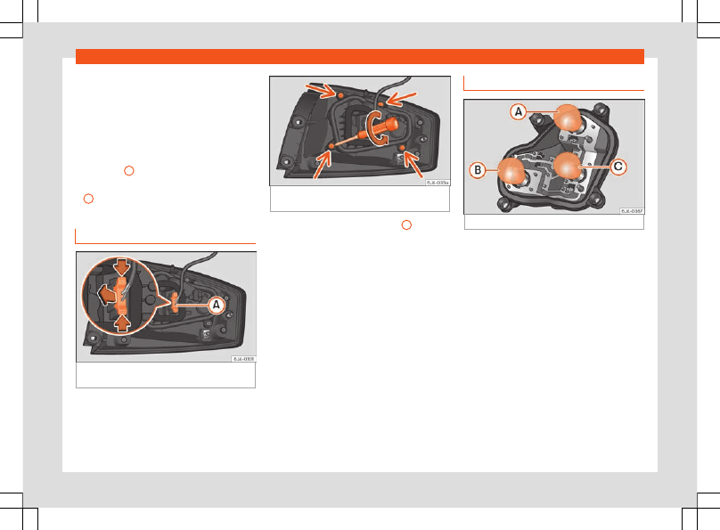
Removing the bulb holder

Fig. 99 

Light connector at the rear of the rear

light unit.

Fig. 100 

Retaining screws on reverse side of

rear light unit.

Disconnect the light connector 

A

››› 

Fig. 99

 by moving its side levers (arrows)

and pulling the connector outwards.

Place the light on a level, horizontal surface
on top of a soft cloth so as not to scratch
the outer glass.

Unscrew the four retaining screws from the
bulb holder anti-clockwise using a screw-
driver or a Torx 20 key (T20) from the vehi-
cle tool kit 

››› 

Fig. 100

. Take care not to lose

the bulb holder retaining screws.

Changing bulbs

Fig. 101 

Position of the bulbs in the bulb holder

The bulbs are secured with a bayonet fasten-
er. The table below gives an overview of the
bulb positions.

Lightly press the defective bulb into the
bulb holder, then turn it anti-clockwise and
remove it.

Fit the new bulb, pressing it into the bulb
holder and turn it clockwise as far as it will
go.

Use a cloth to remove any fingerprints from
the glass part of the bulb.

Check that the new bulb works properly.

Replace the bulb holder.

Screw in the bulb holder using the four
screws, turning them clockwise.

»

91

Emergencies

Position of the bulbs

››› 

Fig. 101

Bulb function

A

Turn signals: PY21W NA LL

B

Side lights-brake lights: P21/5W

C

Position: P21/5W

Note

Check the condition of the seal. If dam-
aged, a replacement can be acquired from
an Official Service.

Fitting the rear light

Fig. 102 

Fit the tail light unit.

Fig. 103 

Fit the tail light unit.

Make sure the connector is correctly in
place.

Press the rear light unit backwards (driving
direction) by fitting the fastenings into the
rubber mountings 

››› 

Fig. 102


A

.

Take the screwdriver or a Torx 20 key (T20)
from the vehicle tool kit and tighten (turning
clockwise 

››› 

Fig. 103

) the two retaining

screws that secure the front of the light.

Changing tail lights (on the
rear lid)

Removing the bulb holder

1)

Fig. 104 

Remove the cover from the rear lid.

1)

For rear-lid LED rear lights, only the reverse and

retro fog bulb can be replaced. The illustrations in
the manual correspond to the bulb version and
do not correspond exactly to the LED version.

92

Fuses and bulbs

Fig. 105 

Remove the bulb holder.

The rear lid must be open to change the
bulbs.

You can access the bulb holder for the inner
tail lights through the inside of the rear lid.

Check which of the bulbs is defective.

Open the cover to access the lights, turning
it by hand in the direction indicated by the
arrows.

Access the lights by disconnecting the con-
nector 

1


››› 

Fig. 105


 and unscrewing

the bulb holder 

››› 

Fig. 105


. Take care not

to lose the bulb holder retaining screw.

Change the bulbs 

››› 

page 93

.

Changing bulbs

Fig. 106 

Position of the bulbs in the bulb hold-

er

The bulbs are secured with a bayonet fasten-
er. The table below gives an overview of the
bulbs 

››› 

table on page 93

.

Lightly press the defective bulb into the
bulb holder, then turn it anti-clockwise and
remove it.

Fit the new bulb, pressing it into the bulb
holder and turn it clockwise as far as it will
go.

Use a cloth to remove any fingerprints from
the glass part of the bulb.

Check that the new bulb works properly.

Re-install the bulb holder 

››› 

page 93

.

Screw in the bulb holder.

Position of the bulbs

››› 

Fig. 106

Bulb function

A

Reversing lights: P21W

B

Side lights: R5W LL

C

Fog lights: P21W

Note

One of the two sides may not be fitted with
a fog light, depending on the country and
type of driving. In this case, the hole for the
light is covered.

Fitting the bulb-holder

Position the bulb holder on the tail light and
align it so that it is securely seated.

Screw in the bulb holder using the corre-
sponding screw.

Make sure the connector is correctly in
place.

Close the inner trim cover.

»

93

Emergencies

Note

Check the condition of the seal. If dam-
aged, a replacement can be acquired from
an Official Service.

Changing the side and num-
ber plate bulbs

Side turn signals

Fig. 107 

Turn signal integrated in the rear view

mirror

The side turn signals are LEDS and are inte-
grated in the exterior mirrors.

In case of failure, go to an authorised work-
shop to have them replaced.

Changing the bulb on the number
plate

Fig. 108 

Removing number plate light

Fig. 109 

Changing the bulb.

Removing the bulb holder

Unscrew the screws to remove the bulb

››› 

Fig. 108

.

Remove the bulb, moving it in the direction

of the arrow and outwards 

››› 

Fig. 109

.

Installation involves all of the above steps in

reverse sequence.

Note

Depending on how equipped the vehicle is,
the number plate lights may be LEDs. LEDs
have an estimated life that exceeds than
that of the car. If a light with LEDs fails, go
to an authorised workshop for replace-
ment.

94

Operation

Fig. 110 

Interior.

96

Controls and displays

Operation

Controls and displays

General instrument panel

Electric window controls

 . . . . . . . . . . . . .

119

Control for adjusting electric exteri-
or mirrors

 . . . . . . . . . . . . . . . . . . . . . . . . . . . . .

130

Air vents

 . . . . . . . . . . . . . . . . . . . . . . . . . . . . . .

147

Multifunction switch lever:

Turn signals, headlights, parking
lights, headlight flasher

 . . . . . . . . . . . .

122

Cruise control

 . . . . . . . . . . . . . . . . . . . . . .

217

Steering wheel:

With horn

With the driver front airbag

 . . . . . . . .

16

With controls for audio, navigation
system and telephone

 . . . . . . . . . . . . .

103

General instrument panel: Instru-
ments and warning lamps

 . . . . . . . . . . .

97

Multifunction switch lever:

Multifunction display

 . . . . . . . . . . . . . .

27

Windscreen wipers and wind-
screen washers

 . . . . . . . . . . . . . . . . . . . .

129

Air vents

 . . . . . . . . . . . . . . . . . . . . . . . . . . . . . .

147

Depending on the equipment:

Audio system

1

2

3

4

5

6

7

8

9

Navigation system

Hazard warning lights switch

 . . . . . . . .

125

Control lamp for deactivated front
passenger airbag in centre con-
sole.

 . . . . . . . . . . . . . . . . . . . . . . . . . . . . . . . . . . .

73

Front passenger airbag switch

 . . . . . .

73

Depending on the equipment, glove
compartment with:

 . . . . . . . . . . . . . . . . . . .

135

CD player* and/or SD card*

 . . . . .

175

Front passenger airbag

 . . . . . . . . . . . . . .

16

Headlight switch

 . . . . . . . . . . . . . . . . . . . . .

121

Headlight range control

 . . . . . . . . . . . . .

121

Lever for unlocking the bonnet

 . . . . . .

13

Fuse compartment

 . . . . . . . . . . . . . . . . . . .

84

Steering column adjustment lev-
er

 . . . . . . . . . . . . . . . . . . . . . . . . . . . . . . . . . . . . .

16

Ignition lock

 . . . . . . . . . . . . . . . . . . . . . . . . . .

197

USB/AUX-IN input.

 . . . . . . . . . . . . . . . . . . . .

195

Depending on the equipment:

Gear lever (manual gearbox)

 . . . . .

203

Selector lever (automatic gear-
box)

 . . . . . . . . . . . . . . . . . . . . . . . . . . . . . . . . .

205

Depending on the equipment:

Drink holder

 . . . . . . . . . . . . . . . . . . . . . . . .

137

Ashtray holder

 . . . . . . . . . . . . . . . . . . . . .

138

Storage space

 . . . . . . . . . . . . . . . . . . . . . . .

135

Depending on the equipment, con-
trols for:

10

11

12

13

14

15

16

17

18

19

20

21

22

23

24

25

Driver heated seat

 . . . . . . . . . . . . . . . . .

132

Park assist system

 . . . . . . . . . . . . . . . . .

222

Central lock button

 . . . . . . . . . . . . . . . .

113

Heated rear window

 . . . . . . . . . . . . . . .

127

Start-Stop system

 . . . . . . . . . . . . . . . . .

215

Front passenger heated seat

 . . . . .

132

Depending on the equipment:

Heating controls

 . . . . . . . . . . . . . . . . . . .

148

Air conditioning controls

 . . . . . . . . . . .

149

Climatronic control

 . . . . . . . . . . . . . . . .

151

Note

The location of the controls of right-hand
drive cars differs slightly from the location
shown here 

››› 

Fig. 110

. However, the sym-

bols correspond to the respective controls.

26

97

Operation

Instruments and warning lamps

Instruments

View of instrument panel

Fig. 111 

Instrument panel, on dash panel.

Details of the instruments 

››› 

Fig. 111

:

Revolution counter

 (with the engine run-

ning, in hundreds of revolutions per mi-
nute).
The beginning of the red zone of the rev
counter indicates the maximum speed in
any gear after running-in and with the en-
gine hot. However, it is advisable to

1

change up a gear or move the selector
lever to 

D

 (or lift your foot off the acceler-

ator) before the needle reaches the red
zone 

››› 

.

Engine coolant temperature display

››› 

page 247

Displays on the screen

.

2

3

Adjuster button and display

››› 

page 101

.

Speedometer

.

Fuel gauge


››› 

page 102

.

WARNING

Any distraction may lead to an accident,
with the risk of injury.

4

5

6

98

Instruments and warning lamps

Do not operate the instrument panel con-

trols when driving.

CAUTION

To prevent damage to the engine, the rev

counter needle should only remain in the
red zone for a short period of time.

When the engine is cold, avoid high revs

and heavy acceleration and do not make
the engine work hard.

For the sake of the environment

Changing up a gear in time reduces fuel
consumption and noise.

Revolution counter

The rev counter indicates the number of en-
gine revolutions per minute 

››› 

Fig. 111


1

.

Together with the gear-change indicator, the
rev counter offers you the possibility of using
the engine of your vehicle at a suitable
speed.

The start of the red zone on the dial indicates
the maximum engine speed which may be
used briefly when the engine is warm and af-
ter it has been run in properly. Before reach-
ing this range, you should change to a higher
gear for vehicles with a manual gearbox or
for automatic gearboxes put the selector lev-

er in “D” or take your foot off the accelerator
pedal.

We recommend that you avoid high revs and
that you follow the recommendations on the
gear-change indicator. Consult the addition-
al information in 

››› 

page 208

.

CAUTION

Never allow the rev counter needle 

1

››› 

Fig. 111

 to go into the red zone on the

scale for more than a very brief period, oth-
erwise there is a risk of engine damage.

For the sake of the environment

Changing up a gear early will help you to
save fuel and minimise emissions and en-
gine noise.

Indications on the display

A variety of information can be viewed on the
instrument panel display 

››› 

Fig. 111 

3

 de-

pending on the vehicle equipment:

Bonnet, rear lid and doors open

››› 

page 31

.

Information and warning texts.

Mileage.

Time.

Navigation instructions.

Outside temperature.

Compass.

Shift lever position 

››› 

page 205

.

Recommended gear (manual gearbox)

››› 

page 208

.

Multifunction display (MFD) and menus with

different setting options 

››› 

page 27

.

Service interval display 

››› 

page 33

.

Second speed display 

››› 

page 100

.

Speed warning function 

››› 

page 32

.

Start-Stop system status display

››› 

page 215

.

Low consumption driving status 

››› 

page 100

Identifying letters on engine (LDM)

››› 

page 100

.

Distance travelled

The 

odometer

 registers the total distance

travelled by the car.

The 

odometer

 (

trip

) shows the distance

travelled since the last odometer reset. The
last digit of the trip recorder indicates distan-
ces of 100 metres or one tenths of a mile.

Briefly press the button 

››› 

Fig. 111


4

 to re-

set the trip recorder to 0.

Keep the button 

4

 pressed for about 3

seconds and the previous value will be dis-
played.

»

99

Operation

Time

To set the time, keep the button 

››› 

Fig. 111

4

 pressed for more than 3 seconds to select

the hour or minute display.

To continue setting the time, press the up-

per or lower part of the button 

4

. Hold but-

ton down to scroll through the numbers
quickly.

Press the button 

4

 again in order to finish

setting the time.

The time can also be set on the Easy Con-
nect system using the 



 button and the

function button 

SETTINGS > Date and

time


››› 

page 24

.

Compass

With the ignition on and the navigation sys-
tem on, the cardinal point corresponding to
the direction of travel of the vehicle is dis-
played on the instrument panel.

Selector lever position

The selected gear is displayed on the side of
the selector lever and on the instrument pan-
el display. In positions 

D

 and 

S

, and with the

Tiptronic, the corresponding gear is also dis-
played.

Outside temperature display

If the outside temperature is lower than ap-
proximately +4°C (+39°F), the “ice crystal

symbol” 

 on the outside temperature dis-

play also lights up. This symbol remains lit un-
til the outside temperature exceeds +6°C
(+43°F) 

››› 

.

When the vehicle is stationary, when the aux-
iliary heater is switched on or when driving at
very low speeds, the outside temperature in-
dicated may be higher than the actual tem-
perature due to the heat produced by the en-
gine.

The margin of measurement ranges from
-45°C (-49°F) to +76°C (+169°F).

Recommended gear (manual gearbox)

The recommended gear in order to save fuel
is displayed on the instrument panel while
you are driving 

››› 

page 208

.

Second speed display (mph or km/h)

In addition to the speedometer, the speed
can also be displayed in a different unit of
measurement (in miles or in km per hour).

This option cannot be deactivated in models
destined for countries in which the second
speed must always be visible.

The second speed display can be adjusted in
the Easy Connect system by means of the



 button and the function button 

SETTINGS

> Units


››› 

page 24

.

Speed warning

When the speed setting is exceeded, this will
be indicated on the instrument panel display.
This is very useful, for example when using
winter tyres that are not designed for driving
at the maximum speed of the vehicle

››› 

page 32

.

The speed warning settings can be adjusted
in the Easy Connect system by means of the



 button and the function button 

SETTINGS

> Driver Assistance


››› 

page 24

.

Start-Stop operating display

Updated information relating to the status is
displayed on the instrument panel

››› 

page 215

.

Low consumption driving status 

*

Depending on the equipment, when driving,
the 

 display appears on the instrument

panel when the vehicle is in low consumption
status.

Identifying letters on engine (LDM)

Hold the button 

››› 

Fig. 111


4

 down for more

than 15 seconds to display the identifying let-
ters of the vehicle engine (LDM). To do this,
the ignition must be switched on and the en-
gine switched off.

100

Instruments and warning lamps

WARNING

Observe the safety warnings 

››› 

 in Con-

trol and warning lamps on page 103

.

WARNING

Even though outside temperatures are
above freezing, some roads and bridges
may be icy.

At outside temperatures above +4°C

(+39°F), even when the “ice crystal sym-
bol” is not visible, there may still be patch-
es of ice on the road.

The outside temperature sensor takes a

guideline measurement.

Note

Different versions of the instrument panel

are available and therefore the versions
and instructions on the display may vary. In
the case of displays without warning or in-
formation texts, faults are indicated exclu-
sively by the warning lamps.

Depending on the equipment, some set-

tings and instructions can also be carried
out in the Easy Connect system.

When several warnings are active at the

same time, the symbols are shown succes-
sively for a few seconds and will stay on
until the fault is rectified.

Odometer

Fig. 112 

Instrument panel: odometer and reset

button.

The distance covered is displayed in “kilome-
tres” or miles “m”. It is possible to change the
measurement units (kilometres “km”/miles
“m”) in the radio/Easy Connect*

››› 

page 24

.

Odometer/trip recorder

The odometer shows the total distance cov-
ered by the vehicle.

The trip recorder shows the distance that has
been travelled since it was last reset. It is used
to measure short trips. The last digit of the trip
recorder indicates distances of 100 metres or
tenths of a mile.

The trip recorder can be set to zero by press-
ing 

0.0/SET


››› 

Fig. 112

.

Fault display

If there is a fault in the instrument panel, the
letters 

DEF

 will appear in the trip recorder dis-

play. Have the fault repaired immediately, as
far as is possible.

Coolant temperature gauge

Fig. 113 

Instrument panel: coolant tempera-

ture gauge

For vehicles with no coolant temperature
gauge, a control lamp 

 appears when the

coolant temperatures is high 

››› 

page 248

.

Please note 

››› 

.

The coolant temperature gauge only works
when the ignition is switched on 

››› 

Fig. 113

. In

order to avoid engine damage, please read
the following notes for the different tempera-
ture ranges.

»

101

Operation

A

 – Cold zone

If only the diodes in the lower part of the
scale light up, this indicates that the engine
has not yet reached operating temperature.
Avoid high revs and heavy acceleration and
do not make the engine work hard.

B

 - Normal temperature

If in normal operations, the diodes light up un-
til the central zone, it means that the engine
has reached operating temperature. At high
outside temperatures and when making the
engine work hard, the diodes may continue
lighting up and reach the upper zone. This is
no cause for concern, provided the control
lamp 

 does not light up on the instrument

panel digital display.

C

 – Heat range

When the LEDs light up in the upper area of
the display and the control lamp 

 appears

on the instrument panel display, the coolant
temperature is too high 

››› 

page 248

.

CAUTION

To ensure a long useful life for the engine,

avoid high revs, driving at high speed and
making the engine work hard for approxi-
mately the first 15 minutes when the engine
is cold. The phase until the engine is warm
also depends on the outside temperature. If
necessary, use the engine oil temperature*

››› 

page 247

 as a guide.

Additional lights and other accessories in

front of the air inlet reduce the cooling ef-
fect of the coolant. At high outside temper-
atures and high engine loads, there is a risk
of the engine overheating.

The front spoiler also ensures proper dis-

tribution of the cooling air when the vehicle
is moving. If the spoiler is damaged this can
reduce the cooling effect, which could
cause the engine to overheat. Seek spe-
cialist assistance.

Fuel level gauge

Fig. 114 

Fuel gauge.

Control lamp

It lights up, and in addition, the

lower diode lights up in red

The fuel reserve level has been reached.
When the fuel level is very low, the lower diode flash-

es in red.

The fuel gauge 

››› 

Fig. 114

 operates only

when the ignition is switched on.

The fuel tank has a capacity of approx. 55 li-
tres. When the needle reaches the fuel re-
serve area there are only approximately 7 li-
tres left in the tank. In the general instrument
panel a warning signal lights up 

 and an

audible signal sounds.

The informative display indicates:

Refuel! Fuel range…km...(miles)

CAUTION

Never completely empty the tank! An irreg-
ularity in the fuel supply system can cause
irregularities when the engine is running.
Unburned fuel can reach the exhaust gas
system, which can cause deterioration of
the catalytic converter.

Note

Some vehicles come fitted with the fuel

gauge on the general instrument panel.

102

Instruments and warning lamps

The message on the display switches off

only after refuelling and carrying out a
short journey.

Control lamps

Control and warning lamps

Read the additional information carefully

››› 

page 34

.

The control and warning lamps are indicators
of warnings, 

››› 

, faults 

››› 

 or certain func-

tions. Some control and warning lamps come
on when the ignition is switched on, and
switch off when the engine starts running, or
while driving.

Depending on the model, additional text
messages may be viewed on the instrument
panel display. These may be purely informa-
tive or they may be advising of the need for
action 

››› 

page 98

.

Depending upon the equipment fitted in the
vehicle, instead of a warning lamp, some-
times a symbol may be displayed on the in-
strument panel.

When certain control and warning lamps are
lit, an audible warning is also heard.

WARNING

If the warning lamps and messages are ig-
nored, the vehicle may stall in traffic, or
may cause accidents and severe injuries.

Never ignore the warning lamps or text

messages.

Stop the vehicle safely as soon as possi-

ble.

Park the vehicle away from traffic and

ensure that there are no highly flammable
materials under the vehicle that could
come into contact with the exhaust system
(e.g. dry grass, fuel).

A faulty vehicle represents a risk of acci-

dent for the driver and for other road users.
If necessary, switch on the hazard warning
lamps and put out the warning triangle to
advise other drivers.

Before opening the bonnet, switch off the

engine and allow it to cool.

In any vehicle, the engine compartment is

a hazardous area and could cause severe
injuries 

››› 

page 244

.

CAUTION

Failure to heed the control lamps and text
messages when they appear may result in
faults in the vehicle.

Multi-function steering
wheel*

General information

The steering wheel includes a multifunction
module from where it is possible to control
the audio, telephone and radio/navigation
functions without needing to distract the driv-
er.

There are two versions of the multifunction
module:

Voice-controlled audio, phone and navi-

gation version

: for controlling the audio

functions available (radio, audio CD, MP3,
iPod

®1)

, USB

1 )

, SD

1 )

) and Bluetooth system

from the steering wheel.

Voice-controlled audio, phone and navi-

gation version

: for controlling the audio

functions available (radio, audio CD, MP3,
iPod

®1 )

, USB

1 )

, SD

1 )

) and Bluetooth system

from the steering wheel.

1)

Depending on the vehicle equipment.

103

Operation

Operating the audio, telephone and navigation system with voice control

Fig. 115 

Controls on the steering wheel.

Button

Radio

Media (except AUX)

AUX

Telephone

a)

Navigation

a)

A

Turn

Turn volume up/down. You do
not need to be in audio mode
(radio).

Turn volume up/down. You do
not need to be in audio mode
(media).

Turn volume up/down. You do
not need to be in audio mode
(media).

Turn volume up/down. You do
not need to be in telephone
mode.

Turn announcement volume
up/down. You do not need to
be in navigation mode but
there has to be an announce-
ment active when you adjust

the volume.

A

Press

Mute volume.

Mute volume.

Mute volume.

Mute incoming call.

Mute the current navigation

announcement.

B

a)

Activate/deactivate voice control.
This function can be used from any mode (audio, media, navigation, assistants, vehicle status, travel data). When the system is in telephone mode this button’s

function is deactivated during the ongoing call, and without Radio/Media functionality (except AUX).

C

 / 

D

Search for the previous/next
station

b)

.

Short press:

 Switch to the

previous/next song.
 

Hold down:

 Fast rewind/for-

ward

c)

.

No function

– There is no active call:

 Ra-

dio/Media functionality (ex-
cept AUX)
 

– Active call:

 no function

No function for the other

modes (navigation, assis-
tants, vehicle status, travel

data).

E

 / 

F

a)

Change instrument panel menu.
This function can be used from any mode (audio, media, navigation, assistants, vehicle status, travel data).

104

Instruments and warning lamps

Button

Radio

Media (except AUX)

AUX

Telephone

a)

Navigation

a)

G

Coloured instrument panel:

 change to the previous menu.

Monochrome Instrument panel:

 switch to the previous function.

H

Turn

Coloured instrument panel:

List of stations available (on-

ly if the instrument panel is in
audio menu).

Coloured instrument panel:

next track (only if the instru-

ment panel is in audio menu).

No function

– There is no active call:

 List

of last calls.
 

– Active call:

 access the call

options list (call on hold,
hang up, mute microphone,
private number, etc.).

– Active route:

 access the

view to halt guidance to des-

tination.


– No active route:

 list of previ-

ous destinations.

H

Press

Acts on the instrument panel or confirms the instrument panel menu option depending on the menu option.

a)

According to the vehicle's equipment package.

b)

This action can be performed when you are listening to the radio; there is no need to be in audio-radio mode.

c)

These actions can be performed when you are listening to media; there is no need to be in audio-radio mode.

105

Operation

Operating the audio, telephone and navigation system with voice control

Fig. 116 

Controls on the steering wheel.

Button

Radio

Media (except AUX)

AUX

Telephone

a)

Navigation

a)

A

Turn

Turn volume up/down. You do
not need to be in audio mode
(radio).

Turn volume up/down. You do
not need to be in audio mode
(media).

Turn volume up/down. You do
not need to be in audio mode
(media).

Turn volume up/down. You do
not need to be in telephone
mode.

Turn announcement volume
up/down. You do not need to
be in navigation mode but
there has to be an announce-
ment active when you adjust

the volume.

A

Press

Mute volume.

Mute volume.

Mute volume.

Mute incoming call.

Mute the current navigation

announcement.

B

a)

– Incoming call:

 pick up (short press), reject (long press).

– Ongoing call:

 hang up (short press).

– No incoming/ongoing call:

 open phone menu (short press), repeat last ongoing call (long press).

These functions can be carried out on any mode (audio, media, navigations, assistants, vehicle status, travel data).

C

 / 

D

Search for the previous/next
station

b)

.

Short press:

 Switch to the

previous/next song.
 

Hold down:

 Fast rewind/for-

ward

c)

.

No function

– There is no active call:

 Ra-

dio/Media functionality (ex-
cept AUX)


– Active call:

 no function

No function for the other
modes (navigation, assis-
tants, vehicle status, travel
data).

E

 / 

F

a)

Change instrument panel menu.
This function can be used from any mode (audio, media, navigation, assistants, vehicle status, travel data).

106


Content      ..     4      5      6      7     ..