SAAB 9000. Manual - part 39


  Index      Saab     SAAB 9000 4-cyl 1985 to 1998 (C to S registration) - Service and Repair Manual


Search            copyright infringement  


Content   ..  37  38  39  40   ..


SAAB 9000. Manual - part 39


9•6 Braking system

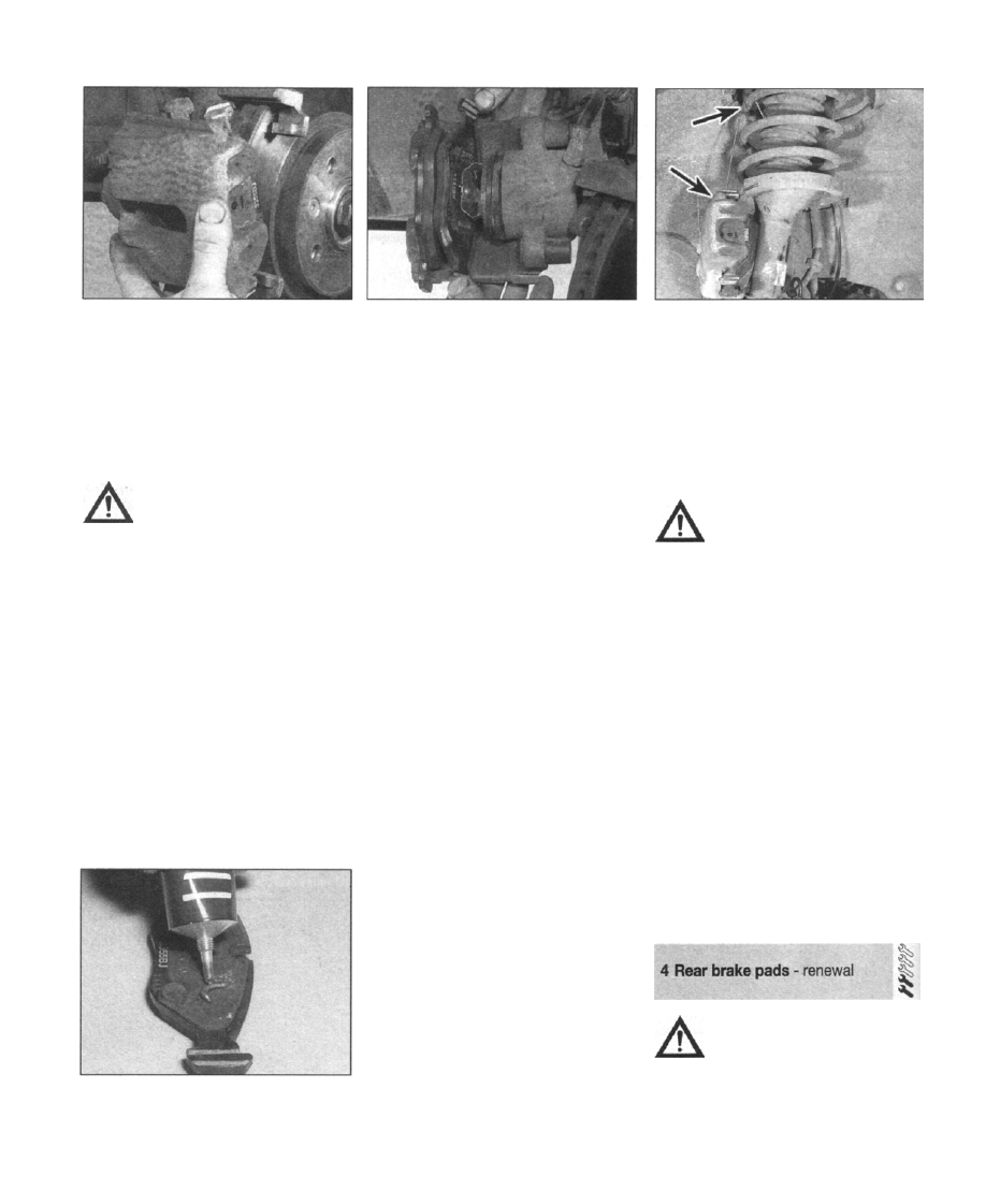
3.10a Take the weight of the hydraulic

body, and lift it away from the carrier

brake pad from the hydraulic body, by prising

the anti-rattle spring attached to its backplate
out of the piston. Lift out the outboard brake

pad (see illustrations).
11
 Attach a cable-tie or a length of welding
rod to a part of the hydraulic body casting,

and suspend it from a convenient point on the
suspension (see illustration).

Caution: Do not let the hydraulic
body dangle by the brake hose.

12 Remove the pads from the second caliper
in the same manner.
13 Clear the dust and debris from the caliper

surfaces, using a brush and brake cleaner
fluid. Avoid inhaling the airborne dust.

14 Examine piston seals for signs of leaking

or deterioration, and the piston itself for signs
of wear or damage. With the hydraulic body
removed, check that the guide pins slide freely
in their bores, without excessive play.

Pad inspection - all calipers

15 Measure the depth of the friction material
remaining on each pad. If any of the pads has

worn down below its service limit (see

"Specifications"), then the complete set of four

pads (both roadwheels) must be renewed.
Similarly, if any of the pads has been
contaminated with grease or oil, it is not
possible to clean and re-use it; the whole set

3.16 Apply a small quantity of copper-

based brake grease to the metal backing

plates of the pads; but do not allow any to

come into contact with the friction material

3.1Ob Remove the inboard brake pad from

the hydraulic body by prising the anti-rattle

spring attached to its backplate out of the

piston

must be renewed. If the pads have been
contaminated, identify and rectify the cause
before fitting new pads. If all the pads are still
serviceable, clean them thoroughly using a
brush (ideally, a fine wire brush) and brake
cleaning fluid. Pay particular attention to the
metal backplate, where the pad contacts the
caliper. Examine the surface of the friction
material; carefully prise out any fragments that
have become embedded in it.
16 Apply a small quantity of copper-based
brake grease to the metal backing plates of the
pads; do not allow any to come into contact

with the friction material (see illustration).
17
 It is good practice to examine the
condition of the brake discs when inspecting
or renewing the pads; refer to Section 7 for
guidance.

Pad fitting - Girling caliper

18 At the first caliper, slide the pads into
position with the friction material facing the
brake disc.
19 Pivot the caliper hydraulic body down into
position. If the pads bind against the disc,

apply pressure to the inboard pad with a pair
of grips to retract the piston back into the
caliper.
20 Refit and tighten the guide pin retaining
bolt.
21 Fit the brake pads to the second caliper in
the same manner.
22 Depress the brake pedal several times;

this will pressurise the braking system and

bring the pads into contact with the disc. If the
pedal has a developed a spongy feel, air may
have entered the system when the pads were
being removed - refer to Section 2 for
guidance in bleeding the system.

23 Refit the roadwheels, lower the vehicle to
the ground and tighten the bolts to the correct
torque.
24 Top-up level of brake fluid in the reservoir
to the "MAX" mark, and refit the cap.

Pad fitting -ATE caliper

25 Fit the outboard pad to the first caliper by
sliding the backplate locating lugs into the
corresponding grooves in the carrier. Ensure

3.11 Hydraulic body suspended from the

coil spring on a length of wire

that the friction material surface rests squarely
against the disc surface.
26 Fit the inboard pad to the hydraulic body
by pressing the tangs of its anti-rattle spring
into the hollow piston.
27 Using G-clamps or pipe grips, force the
piston and inboard pad back into the hydraulic
body. With the pad retracted, the hydraulic
body can be refitted to the carrier.

Caution: Keep an eye on the level

in the brake fluid reservoir as you
retract the pads, to ensure that
the displaced fluid does not
cause it to overflow.

28 Slacken and remove the G-clamps/grips,
allowing the piston and pads settle in position.

Lightly lubricate the guide pins with a smear of
anti-seize grease and refit them, tightening

them to the correct torque (refer to
Specifications). Refit the dust caps.
29 Fit the spring clip in position, locating the
ends of it in the holes provided in the hydraulic
body.
30 Fit the pads to the second caliper in the
same manner.
31 Depress the brake pedal several times;
this will pressurise the braking system and
bring the pads into contact with the disc. If the
pedal has a developed a spongy feel, air may
have entered the system when the pads were
being removed - refer to Section 2 for
guidance in bleeding the system.
32 Refit the roadwheels, lower the vehicle to

the ground and tighten the bolts to the correct
torque.
33 Top-up level of brake fluid in the reservoir
to the "MAX" mark and refit the cap.

Warning: Refer to the warning at
the start of Section 3 before

starting work.

Note: As the handbrake and footbrake are

self-adjusting, it is not possible to assess brake
pad wear from the amount of pedal or lever

travel - a visual inspection must be carried out,

as described in Chapter 1.

Braking system 9•7

4.2a At the first caliper, remove the dust

plug from the adjusting screw drilling on

the hydraulic body

1 Park the vehicle on a firm, level surface.
Chock the front wheels, and select first gear

manual transmission) or "Park" (automatic

transmission) - do not apply the handbrake.

Raise the rear of the vehicle, rest it securely on
axle stands, and remove both rear roadwheels
- refer to "Jacking, towing and wheel
changing" for guidance.
2 At the first caliper, unscrew the dust plug

from the adjusting screw drilling on the
hydraulic body. Using an Allen key, turn the
adjusting screw anti-clockwise to the end of

its travel - this will cause the piston to be

retracted fully into the hydraulic body, drawing
the brake pad away from the disc (see
illustrations).
3
 Prise out the two dust caps, then using a
7 mm hex bit and socket wrench, slacken and

withdraw the caliper guide pins (see

illustrations).

4 Using a screwdriver, lever the retaining

spring clip off the caliper (see illustration).
5
 Lift the hydraulic body away from the
carrier, then relieve the spring tension on the
handbrake lever, and release the handbrake
cable from it (see illustration).

6 Extract the brake pads from the hydraulic

body. Note that the inboard pad must be
prised away from the piston, as it is retained
by an anti-rattle spring, attached to the pad

ackplate (see illustration).

7 Hang the hydraulic body casting from a rigid
point on the vehicle's suspension, using
cable-ties or wire (see illustration 3.11). Do not

4.4 Using a screwdriver, lever the retaining

spring clip (arrowed) off the caliper

4.2b Using an Allen key, turn the adjusting

screw anti-clockwise to the end of its

travel

allow it to dangle by the brake hose, as this
will undoubtedly cause damage to the hose.
8 Remove the pads from the caliper at the
other roadwheel in the same manner.
9 Examine the caliper piston seals for signs of
leaking or deterioration, and the piston itself

for signs of wear or damage. Clear the dust
and debris from the hydraulic body and carrier
surfaces, using a brush and brake cleaner
fluid. Avoid inhaling the airborne dust by
wearing an approved filtration mask.

10 With the hydraulic body removed, check

that the guide pins slide freely in their bores,
without excessive play.

11 Measure the depth of the friction material
remaining on each pad. If any of the pads has

worn down below its service limit (see
"Specifications"), then the complete set of four
pads (both roadwheels) must be renewed.
Similarly, if any of the pads has been
contaminated with grease or oil, it is not
possible to clean and re-use it; the whole set
must be renewed. If the pads have been
contaminated, or have worn unevenly, identify
and rectify the cause before fitting new pads.
12 If all the pads are still serviceable, clean
them thoroughly using a brush (ideally, a fine
wire brush) and brake cleaning fluid. Pay
particular attention to the metal backplate,
where the pad contacts the carrier/piston.
Examine the surface of the friction material;
carefully prise out any fragments that have

4.3a Prise out the two dust caps ...

4.3b ... then using a 7 mm hex bit and

socket wrench, slacken ...

4.3c ... and withdraw the caliper guide

pins

4.5 Lift the hydraulic body away from the

carrier, then relieve the spring tension on

the handbrake lever, and release the

handbrake cable from it

4.6 Extract the brake pads from the

hydraulic body. Note that the inboard pad

must be prised away from the piston, as it

is retained by an anti-rattle spring,

attached to the pad backplate

9•8 Braking system

become embedded in it. Brush out the
grooves if they are clogged
13 It is good practice to examine the condition
of the brake discs when inspecting or renewing

the pads; refer to Section 7 for guidance.

14 Apply a small quantity of copper-based
brake grease to the metal backing plates of the
pads; do not allow any to come into contact with

the friction material (refer to illustration 3.16).

15 Fit the pads to the hydraulic body,
pressing the inboard pad anti-rattle spring into

the hollow of the piston. Fit the hydraulic body
to the carrier.

16 Lubricate the guide pins with a smear of
anti-seize grease, and refit them. Tighten them
securely using a 7 mm hex bit, then refit the
dust caps.
17 Fit the spring clip into place, locating the
ends into the holes provided in the hydraulic
body casting.
18 Using an Allen key, screw in the adjusting
screw until the inboard pad is almost touching
the brake disc.
19 Refit the plug and washer but make sure
that they are thoroughly cleaned before doing
so.
20 Operate the handbrake lever against the
return spring tension and reconnect the
handbrake cable, then refer to Chapter 1 and
adjust the operation of the handbrake.
21 Depress the brake pedal several times;
this will pressurise the braking system and
bring the pads into contact with the disc. If the
pedal has a developed a spongy feel, air may
have entered the system when the pads were
being removed - refer to Section 2 for
guidance in bleeding the system.
22 Refit the roadwheels, lower the vehicle to
the ground, and tighten the roadwheel bolts to
the correct torque.
23 Top-up level of brake fluid in the reservoir
to the "MAX" mark, and refit the cap.

Warning: Refer to the warning

notes at the start of Sections 2
and 3 regarding the safe
handling of brake system
components and fluids.

1 Park the vehicle on a firm, level surface,

then chock the rear wheels and apply the

handbrake. Apply the handbrake, then raise

the front of the vehicle, rest it securely on axle
stands, and remove the appropriate front

roadwheel to expose the caliper requiring
attention. Refer to "Jacking, towing and wheel

changing" for guidance.
2 To allow the caliper to be removed, the
brake hose must be disconnected from it - this
will entail some brake fluid loss. The amount of
fluid lost can be minimised by clamping the
flexible brake hose using a proprietary hose
clamp (see illustration). These are designed
to constrict hoses without pinching the walls
and causing damage - they can be obtained
from motor accessory shops at minimal cost.

Caution: The unprotected jaws of
a G-clamp should not be used, as
they may damage the hose,
leading to premature failure.

Removal

3 Clean the caliper in the area around the
brake hose union with a clean rag. Slacken the
hose union, but do not attempt to unscrew it
completely at this stage, or the hose will
become twisted.
4 Remove the brake pads as described in
Section 3.
5 On models fitted with Girling calipers (see

"Specifications"), prise out the dust cap, and
unscrew the upper guide pin bolt using a

spanner and socket wrench. The hydraulic
body can then be lifted away from the carrier.
6 The hydraulic body can now be detached
from the brake hose; hold the hose still, and
rotate the hydraulic body until the hose union
unscrews from the tapping. Be prepared for
some brake fluid loss - have a small container
or a clean rag ready to catch spills. If the flow
of fluid does not stop after the initial
discharge, check the security and tightness of
the hose clamp.
7 Wipe clean the end of the brake hose and
the tapping in the hydraulic body, and fit them
with dust caps.

If dust caps are not available,
cut the fingers out of an old
rubber glove, and stretch
them over the open end of the

brake pipe, securing them with elastic
bands.

5.2 Brake hose clamp in use

8 Slacken and remove the retaining bolts,
then lower the carrier away from the steering
swivel member.

Overhaul

9 The cleanliness of the work area is of great
importance when dismantling brake system
components. Dirt entering the hydraulic
system may adversely affect the system's
performance, and possibly cause failure.
Select a clean, uncluttered surface to work on;
laying a sheet of plain paper or card on the

surface may help to keep things clean and
easily visible.
10 Clean off all traces of dirt and dust from
the hydraulic body, using a brush.

Warning: Take great care to avoid

inhaling the airborne dust.

11 The piston can be removed from the
cylinder by applying compressed air to the
hydraulic hose tapping. Only low pressure is
required, so that produced by a bicycle or foot
pump should be sufficient. Remove the dust

cap, and couple the pump to the tapping with
an old piece of vacuum or fuel hose to make a
good seal - do not use anything that may
damage the thread inside the tapping. Use a
block of wood as padding to protect the end
of the piston as it is ejected under pressure.
12 Carefully prise the dust cover out from the
cylinder bore, leaving it attached to the piston
- use a plastic instrument that will not damage
the surface of the cylinder. Put the piston and
dust cover to one side.

13 Using the same plastic instrument, lever
out the piston seal from its seat in the cylinder
bore. Avoid scoring the inside of the bore or

the seal seat.

14 Clean all components thoroughly, using
only methylated spirit, isopropyl alcohol or
clean hydraulic fluid as a cleaning agent. Do
not
 use mineral-based solvents such as petrol
or paraffin, as they will attack the hydraulic
system's rubber components. Dry the
components straight after cleaning, using
compressed air or a clean, lint-free cloth. Use
compressed air to blow the fluid passages
clear. If reassembly is not going to be carried
out immediately, remember to refit a dust cap

to the brake hose tapping.

15 Examine all components closely, and
renew any that are worn or damaged. Check
particularly the cylinder bore and piston; if they
are scratched, worn or corroded in any way,

they should be renewed (note that this means
the renewal of the whole hydraulic body
assembly). Check also the condition of the
guide pins and their bores in the hydraulic

body; both pins should be free from damage
and corrosion. After cleaning, they should
form a reasonably tight sliding fit in their
corresponding bores. Renew any component
whose condition is dubious.
16 If the assembly is fit for further use, obtain
an appropriate repair kit; the components are
available from Saab dealers in various
combinations.
17 Renew all rubber seals, dust covers and
caps disturbed on dismantling as a matter of
course; the old items should never be re-used.
18 Before reassembly, ensure that all
components are completely clean and dry.
19 Lubricate the new piston seal with the
grease provided in the kit. Use the same
grease to lubricate the new dust cap.
20 Fit the new piston seal into its seat in the
cylinder; do not use any tools when doing this.
21 Fit the new dust cap to the piston; slide it

Braking system 9•9

5.25a Refit the carrier to the steering swivel

member

5.25c  . . . then tighten them to the specified

torque

over the end that contacts the brake pad, then
pull it down to the other end of the piston.
22 With the hydraulic body laid on the work
surface, offer up the piston to the cylinder
bore. Starting at the lower edge, press the
collar of the dust cap into the cylinder bore,
working around its circumference until the
collar is firmly seated all the way around.
23 The piston can now be pressed into the
cylinder - use care as the piston engages with

the new seal. Note that it may be necessary to
remove the dust cap from the brake hose
tapping as you do this, to allow the air in the
cylinder to escape.

Refitting

24 Reconnect the hydraulic body to the brake
hose by threading the hose union into the
tapping, holding the hose stationary and
rotating the hydraulic body. Do not fully
tighten the union at this stage.
25 Refit the carrier to the steering swivel
member - apply a quantity of thread-locking
compound to the retaining bolts, then insert
and tighten them to the specified torque (see
illustrations).
 On models fitted with Girling
calipers, lift the hydraulic body into position on
the carrier and fit the upper guide pin bolt,
tightening it securely.
26 For all calipers, follow the brake pad
refitting sequence at the end of Section 3, but
do not refit the roadwheel at this stage.

27 With the brake pads fitted, fully tighten the
Drake pipe union.
28 Remove the brake pipe clamp tool.

5.25b Apply a quantity of thread-locking

compound to the retaining bolts  . . .

Referring to Section 2, bleed the system to
expel the air that will have entered the brake
hose when the caliper was removed. If suitable
precautions were taken to minimise fluid loss,
it should only be necessary to bleed the
system at that caliper.
29 Refit the roadwheel, lower the vehicle to

the ground and tighten the bolts to the
specified torque.

Warning: Refer to the warning

notes at the start of Sections 2
and 3 regarding the safe
handling of brake system
components and fluids.

1 Park the vehicle on a firm, level surface.

Chock the front wheels, and select first gear
(manual transmission) or "Park" (automatic
transmission). Release the handbrake. Raise
the rear of the vehicle, rest it securely on axle
stands, and remove the appropriate rear
roadwheel to expose the caliper requiring
attention. Refer to "Jacking, towing and wheel
changing"
 for guidance.
2 To allow the caliper to be removed, the
brake hose must be disconnected from it - this
will entail some brake fluid loss. The amount of

fluid lost can be minimised by clamping the
flexible brake hose using a proprietary hose
clamp (refer to illustration 5.2). These are
designed to constrict hoses without pinching
the walls and causing damage - they can be
obtained from motor accessory shops at
minimal cost.

Caution: The unprotected jaws of
a G-clamp should not be used, as
they may damage the hose,
leading to premature failure.

Removal

3 Clean the caliper in the area around the
brake hose union with a clean rag. Slacken the
hose union, but do not attempt to unscrew it
completely at this stage, or the hose will
become twisted.
4 Remove the brake pads as described in
Section 4.

5 Fit a brake hose clamp tool over the brake
hose, and tighten it. Hold the brake hose
stationary with one hand, and rotate the
hydraulic body with the other, until the hose
union unscrews from its tapping. Be prepared

for some brake fluid leakage; have a small
container or rag ready to catch spills. If the
flow of fluid does not stop after the initial
discharge, check the security and tightness of
the hose clamp.
6 Wipe clean the end of the brake hose and
the tapping in the hydraulic body, and fit them
with dust caps.

If dust caps are not available,
cut the fingers out of an old
rubber glove, and stretch
them over the open brake pipe

end, securing them with elastic bands.

7 Slacken and remove the retaining bolts,
then lower the carrier away from the hub
assembly.

Overhaul

8 The cleanliness of the work area is of great
importance when dismantling brake system
components. Dirt entering the hydraulic
system may adversely affect the system's
performance, and possibly cause failure.
Select a clean, uncluttered surface to work on;
laying a sheet of plain paper or card on the
surface may help to keep things clean and
easily visible.
9 Clean off all traces of dirt and dust from the
hydraulic body, using a brush.

Warning: Take great care to avoid
inhaling the airborne dust.

10 Lay the hydraulic body on the work

surface. Using a blunt screwdriver, lever out
the guide pin spacer sleeves, together with the
dust covers. Avoid scratching the internal
surfaces of the spacer sleeves.
11 Lift the handbrake lever return spring off
its pivot, and put it to one side.
12 Prise off the dust cover retaining ring;
avoid damaging the piston by using a plastic
implement, or a small screwdriver with its
blade wrapped in tape. Pull the dust cover
away from the piston.
13 Using 4 mm Allen key, rotate the adjusting
screw clockwise to force the piston out of the
cylinder. It may be necessary to remove the
dust cap from the brake hose tapping at this
point, to allow air into the cylinder as the
piston is pushed out.
14 Lever the piston seal out of its seat using

the plastic instrument; take care not to score
the surface of the cylinder bore.

15 Clean all components thoroughly, using
only methylated spirit, isopropyl alcohol or

clean hydraulic fluid as a cleaning medium. Do
not
 use mineral-based solvents such as petrol
or paraffin, as they will attack the hydraulic
system's rubber components.


Content   ..  37  38  39  40   ..