SAAB 9000. Manual - part 12
2A•14 Engine in-car repair procedures
9.35 Removing a cylinder head bolt
28 On models fitted with a two-section inlet
manifold, disconnect the air conditioning valve
hose and the crankcase breather hose, and
(where applicable) unbolt the dipstick tube
bracket. Detach the upper inlet manifold from
the hoses, then tilt it to one side and secure
the hoses with cable-ties.
29 Unscrew the inlet manifold-to-cylinder
head mounting bolts, and move the complete
manifold assembly to the rear of the engine
compartment. Recover the gasket. Leave all
wiring, hoses and cables (as applicable)
connected to the inlet manifold assembly.
30 Unbolt and remove the cylinder head
cover, and remove the special split rubber
plugs from the cylinder head. If it is stuck, tap
it gently with the palm of your hand to free it.
31 Using a socket on the crankshaft pulley,
turn the engine until the TDC mark on the
flywheel/driveplate or crankshaft pulley is
aligned with the timing mark on the transmission
or timing cover, and No 1 piston (at the timing
chain end of the engine) is at the top of its
compression stroke. If necessary, refer to
Section 3 for more information. Check also that
the TDC marks on the sprocket ends of the
camshafts are aligned with the corresponding
TDC marks on the camshaft bearing caps.
32 Unscrew and remove the timing chain
tensioner from the rear of the cylinder head.
33 While holding each camshaft stationary
with a spanner on the special flats at the
flywheel/driveplate end of the camshaft,
unscrew the bolts, then withdraw the
sprockets and allow them to rest on the timing
chain guides. Alternatively, remove the
sprockets, after identifying them for position.
Note that on B204/B234 engines, the timing
chain will not come off the crankshaft
sprocket, as there is a retainer located near
the bottom of the sprocket. On B202 engines,
keep the chain on the sprocket by tying it at
the top of the guides.
34 Unscrew and remove the two bolts
securing the timing cover to the cylinder head.
The bolts screw into the bottom of the head.
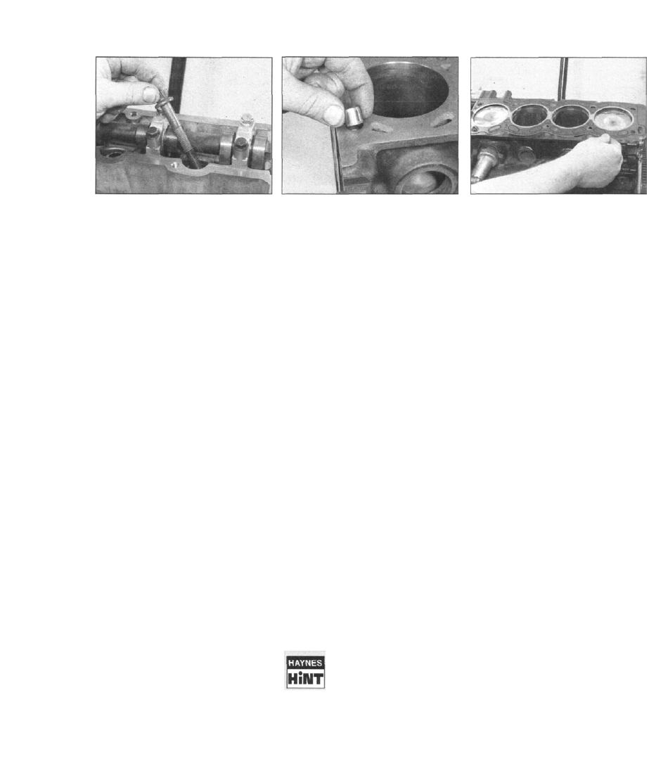
35 Working in the reverse of the sequence
shown in illustration 9.50a, progressively
slacken the ten cylinder head bolts by half a
turn at a time, until all bolts can be unscrewed
by hand (see illustration). The bolts require
9.37 Removing a cylinder head locating
dowel
the use of a Torx socket to unscrew them, as
they have six external splines.
36 With all the cylinder head bolts removed,
check that the timing chain is positioned so
that the pivoting chain guide will not obstruct
removal of the head. Lift the cylinder head
directly from the top of the cylinder block, and
place it on the workbench. If necessary, enlist
the help of an assistant, since the cylinder
head is quite heavy. If the cylinder head is
stuck, try rocking it slightly to free it from the
gasket - do not insert a screwdriver or similar
tool between the gasket joint, otherwise the
contact faces will be damaged. The head is
located on dowels, so do not try to free it by
tapping it sideways.
37 Remove the gasket from the top of the
block, noting the two locating dowels. If the
locating dowels are a loose fit, remove them
and store them with the head for safe-keeping
(see illustration). Do not discard the gasket -
it may be needed for identification purposes.
38 If the cylinder head is to be dismantled for
overhaul, remove the camshafts as described
in Section 8.
Preparation for refitting
39 The mating faces of the cylinder head and
cylinder block must be perfectly clean before
refitting the head. Use a hard plastic or wood
scraper to remove all traces of gasket and
carbon; also clean the piston crowns. Take
particular care during the cleaning operations,
as the soft aluminium alloy is damaged easily.
Also, make sure that the carbon is not allowed
to enter the oil and water passages - this is
particularly important for the lubrication
system, as carbon could block the oil supply
to the engine's components. Using adhesive
tape and paper, seal the water, oil and bolt
holes in the cylinder block.
To prevent carbon entering
the gap between the pistons
and bores, smear a little
grease in the gap. After
cleaning each piston, use a small brush
to remove all traces of grease and
carbon from the gap, then wipe away
the remainder with a clean rag.
9.45 Position a new cylinder head gasket
on the cylinder block
Clean all the pistons in the same way.
40 Check the mating surfaces of the cylinder
block and the cylinder head for nicks, deep
scratches and other damage. If slight, they
may be removed carefully with a file, but if
excessive, machining may be the only
alternative to renewal.
41 If warpage of the cylinder head gasket
surface is suspected, use a straight-edge to
check it for distortion. Refer to Part B of this
Chapter if necessary.
42 Check the condition of the cylinder head
bolts, and particularly their threads, whenever
they are removed. Wash the bolts in suitable
soh/ent, and wipe them dry. Check each for
any sign of visible wear or damage, renewing
any bolt if necessary. Measure the length of
each bolt, and compare with the length of a
new bolt. Although Saab do not actually
specify that the bolts must be renewed, it is
strongly recommended that the bolts are
renewed as a complete set if the engine has
completed a high mileage.
Refitting
43 Where removed, refit the camshafts with
reference to Section 8.
44 Wipe clean the mating surfaces of the
cylinder head and cylinder block/crankcase.
Check that the two locating dowels are in
position on the cylinder block.
45 Position a new gasket on the cylinder
block surface, making sure that it is fitted the
correct way round (see illustration).
46 Check that each camshaft is at its TDC
position - the timing marks are located on the
front of the camshaft, and must be aligned
with the marks on the bearing caps.
47 Check that the TDC "0" mark on the
flywheel/driveplate is still aligned with the
timing mark on the transmission.
48 Check that the timing chain is located
correctly on the chain guides, then carefully
lower the cylinder head onto the block,
aligning it with the locating dowels.
49 Apply a smear of grease to the threads,
and to the underside of the heads, of the
cylinder head bolts. Insert the bolts, and screw
them in finger-tight.
50 Working progressively and in the
sequence shown, tighten the cylinder head