Renault Kangoo (2022 year). Manual in english - page 10
TYRE PRESSURE LOSS WARNING (5/6)
Readjustment of tyre
After each change of wheel/tyre, read-
just the tyre pressure and launch the
7
pressures
reset of the tyre pressure reference
The pressure of the four tyres must
value.
be set when cold (refer to the label lo-
cated on the edge of the driver’s door).
Emergency spare wheel
If tyre pressures cannot be checked
when the tyres are cold, the recom-
If fitted on the vehicle, readjust the tyre
mended pressures should be increased
pressure and launch the reinitialisation
by 0.2 to 0.3 bar (3 PSI).
of the tyre pressure reference value.
Never deflate a hot tyre.
After each reinflation or readjustment of
Tyre repair product and
the tyre pressure, launch the reinitiali-
inflation kit
sation of the tyre pressure reference
value.
Only use equipment approved by the
brand network, or the system risks
being activated late or not operating
Tyre pressure faults
Replacing wheels/tyres
correctly. ➥ 5.4. After using the tyre
The table on the following page lists
Only use equipment approved by the
inflation kit, readjust the tyre pressure
the warning messages which appear
network, otherwise the system risks
and launch the resetting of the tyre
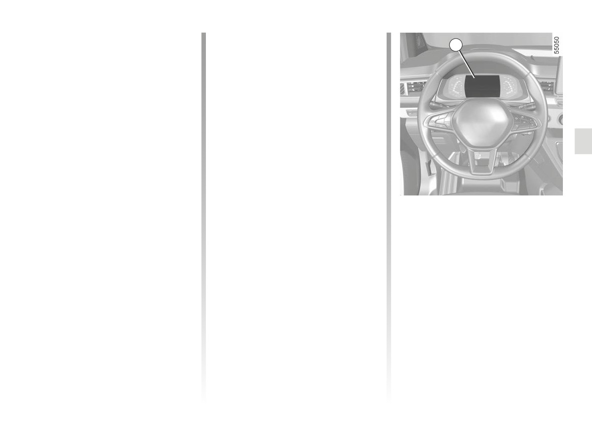
on the instrument panel 7 when the
late activation or incorrect operation.
pressure reference value.
system detects a tyre pressure fault.
➥ 5.13.
2.35

TYRE PRESSURE LOSS WARNING (6/6)
The information on the instrument panel signals any potential tyre pressure faults (e.g. deflated or punctured tyre).
Indicator
Messages
Readings
lights
This indicates that tyre under-inflation or puncture has been detected.
Inflate tyres and init.
Check and adjust the pressure of the four tyres when cold and reset the
system.
This indicates that the reset has been unsuccessful. Check and readjust
Check tyre press and init.
the tyre pressure before re-launching the resetting procedure.
This indicates that the last system reset was carried out over 6 months
Check tyre press and init.
ago or over approximately 6,214 miles (10,000 km). Check and readjust
the tyre pressure before re-launching another resetting procedure.
Check TPW
This indicates a fault in the system. Consult an approved dealer.
This indicates that an emergency spare wheel different in size to the other
four wheels has been fitted to the vehicle. The system remains unavail-
TPW not available
able until a wheel identical in size to the other wheels has been fitted and
the resetting procedure has been carried out.
2.36
TYRE PRESSURE MONITOR (1/5)
1
Resetting the standard level
for the tyre pressures
This should be done:
- when the standard tyre pressure
needs to be changed to adapt to
usage conditions (empty, carrying a
load, motorway driving, etc.);
- after swapping a wheel (however
this practice is not recommended);
- after changing a wheel.
It should always be done after checking
the tyre pressure of all four tyres when
cold.
Tyre pressures must correspond to the
current usage of the vehicle (empty,
If the vehicle is equipped with the func-
carrying a load, motorway driving, etc.).
tion, this system monitors the tyre pres-
sure.
Operating principle
Each wheel (except for the emergency
spare wheel) has a sensor in the infla-
tion valve which periodically measures
the tyre pressure.
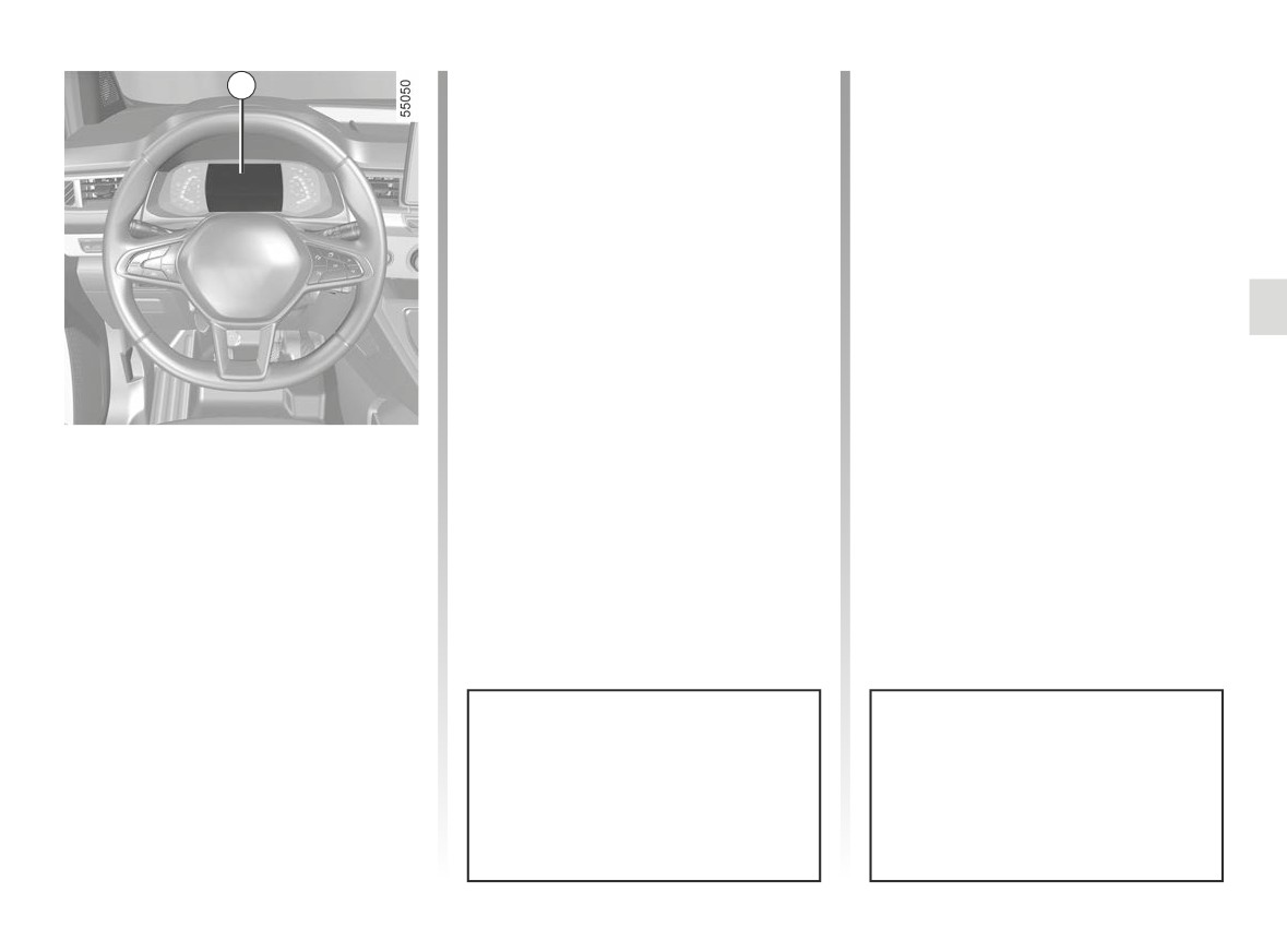
The system displays the current pres-
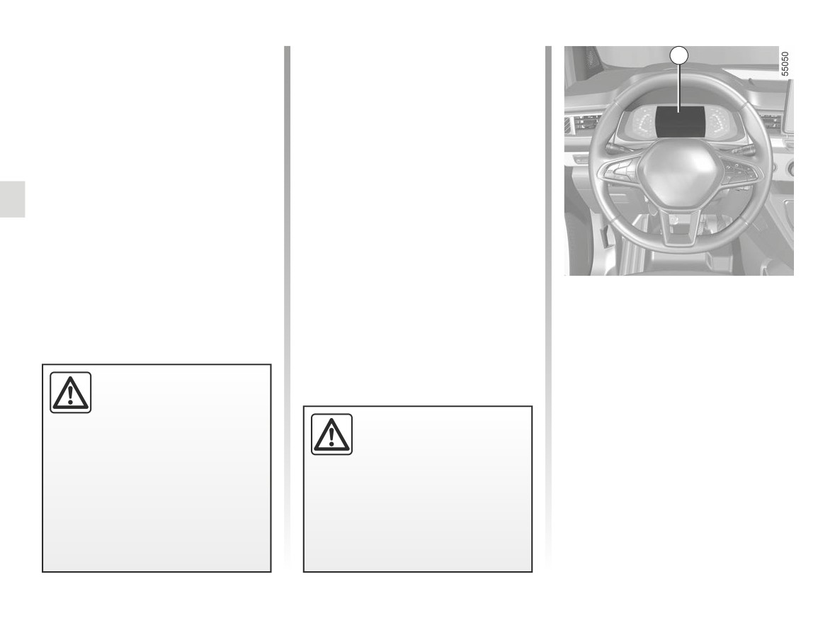
sures on the instrument panel 1 and
alerts the driver in the event of insuffi-
If the vehicle is equipped with a nav-
cient pressure.
If the wheels are swapped, the
igation system, the resetting proce-
system must be reinitialised.
dure may also be carried out using
Consult an approved dealer.
the multimedia screen: please see
the equipment instructions.
2.37
TYRE PRESSURE MONITOR (2/5)
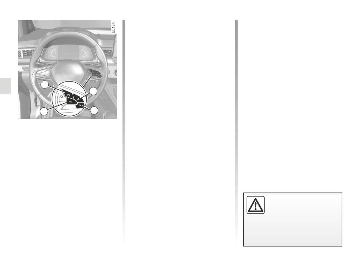
- press and hold (around 3 seconds)
the button 4 to launch the reset. The
flashing tyres followed by the mes-
sages “Learning Tyre Pressures”
and then “Tyres location in progress”
indicates that the reset request for
the tyre pressure reference value
has been acknowledged.
Reset can take several minutes of driv-
ing.
5
2
If the resetting is followed by short
trips, the message “Tyres location in
progress” can remain displayed after
4
3
successive restarts.
Note: the standard tyre pressure
Resetting procedure
cannot be less than that recommended
Ignition on, vehicle stopped:
and indicated on the door frame.
- repeatedly tap the 5 switch as many
times as necessary to reach the “ve-
hicle” tab
;
- briefly press the 2 or 3 switch to
reach the “Tyre Pressure” page;
For your safety, the warning
light
®
requires you
to stop immediately as soon
as traffic conditions allow.
2.38
TYRE PRESSURE MONITOR (3/5)
The table below shows the possible messages related to the tyre resetting procedure.
Steps
Displays
Messages
Readings
(depending on
the vehicle)
1
Tyre pressure init. long press
With the ignition on and the vehicle stationary, start the
resetting the pressure of all four tyres by pressing and
holding the 4 OK switch.
2
Learning Tyre Pressures
The “---” quote marks in front of each wheel will flash to
indicate that the system has registered the tyre pressure
reset for all four wheels.
3
Tyres location in progress
The “---” quote marks in front of each wheel will remain
lit. This system resets the tyre pressure of all four tyres.
You can now drive. The message may remain displayed
during short journeys.
Note: during the reset, tyre pressure monitoring remains
in operation.
4
The pressure value of the four tyres is displayed: the re-
setting procedure is complete and successful.
2.39
TYRE PRESSURE MONITOR (4/5)
Readjustment of tyre
Replacing wheels/tyres
1
pressures
This system requires specific equip-
The pressure of the four tyres must
ment (wheels, tyres, hubcaps, etc.).
be set when cold (refer to the label lo-
➥ 5.13.
cated on the edge of the driver’s door).
Contact an approved Dealer to fit new
If the tyre pressures cannot be checked
tyres and to find out about available ac-
when the tyres are cold, the recom-
cessories compatible with the system
mended pressures should be increased
and available from your dealer net-
by 0.2 to 0.3 bar (3 PSI).
work: the use of any other accessory
Never deflate a hot tyre.
could affect the correct operation of the
system or damage a sensor.
Emergency spare wheel
If the vehicle is equipped with an emer-
gency spare wheel, it will not have a
sensor.
Tyre repair product and
inflation kit
Because the valves are specially de-
signed, only use equipment approved
by the approved network. Please see
the section on ➥ 5.4.
This function is an addi-
tional driving aid.
The function does not take
Tyre pressure faults
the place of the driver. It
Changing a wheel
The table on the following page lists
cannot, therefore, under any cir-
The system may take sev-
the warning messages which appear
cumstances replace the vigilance
eral minutes depending on
on the instrument panel 1 when the
or the responsibility of the driver.
use for the new wheel po-
system detects a tyre pressure fault.
Check the tyre pressures, including
sitions and pressures to be recog-
the emergency spare wheel, once a
nised; check the tyre pressures after
month.
all operations.
2.40
TYRE PRESSURE MONITOR (5/5)
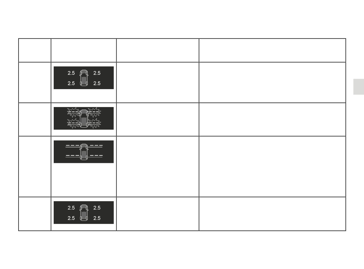
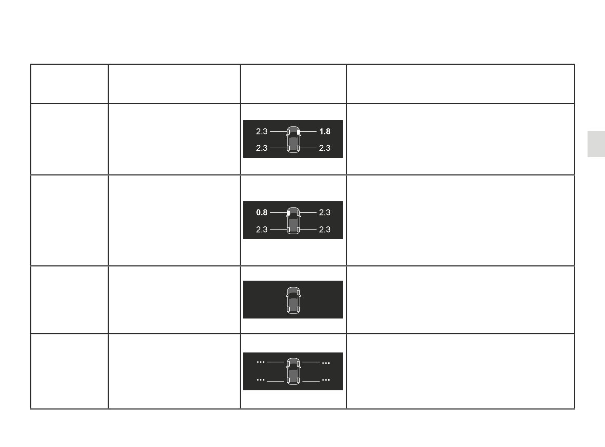
The information on the instrument panel signals any potential tyre pressure faults (e.g. deflated or punctured tyre). For
your safety, the warning light® requires you to stop immediately as soon as traffic conditions allow.
Indicator
Messages
Displays
Readings
lights
(depending on
the vehicle)
The wheel and associated pressure value are dis-
played in yellow.
Adjust Tyre Pressure
This indicates that tyre under-inflation has been de-
tected. Check and adjust the pressure of the four
tyres then reset the system.
The wheel and associated pressure value are dis-
played in red.
This indicates that the tyre concerned is punctured
Puncture
or severely underinflated. Adjust the pressure of the
+®
four tyres while cold and reset the system if the tyre
is deflated. Replace the tyre (or have it replaced) if
it is punctured.
A wheel is no longer displayed.
This indicates that at least one wheel is not fitted with
Check Tyre Pressure Sensors
a sensor (e.g. emergency spare wheel) or that the
sensor is faulty. Consult an approved dealer.
This indicates that the system has not been able to
determine the pressure of each tyre. This may be
Tyre Detection Failure
caused by the use of a sensor not recommended by
an approved dealer. The tyre pressure sensor moni-
toring system remains in operation.
2.41
DRIVING CORRECTION DEVICES AND AIDS (1/6)
Depending on the vehicle, this is com-
posed of:
- anti-lock braking system (ABS);
- the electronic stability control
(ESC) with understeer control,
side winds assistance and trac-
tion control;
- emergency brake assist;
- hill start assist;
- driver assistance with a trailer;
- traction control - “Extended grip”.
Other driving assistance systems are
These functions are an ad-
detailed on the following pages.
ditional aid in the event of
critical driving conditions,
enabling the vehicle behav-
iour to be adapted to suit the driving
conditions.
These functions do not take the
place of the driver. They do not
increase the vehicle’s limits and
should not encourage you to
drive more quickly. Therefore,
they can under no circumstances
replace the vigilance or responsibil-
ity of the driver when manoeuvring
the vehicle (the driver must always
be ready for sudden incidents which
may occur when driving).
2.42
DRIVING CORRECTION DEVICES AND AIDS (2/6)
Anti-lock braking system
Operating faults:
(ABS)
-
and x
lit up on the in-
Under heavy braking, the ABS prevents
strument panel accompanied
the wheels from locking, allowing the
by the messages
“Check ABS”,
stopping distance to be managed and
“WARNING: Check Braking System”
keeping control of the vehicle.
and “Check ESC”: this indicates that
Under these circumstances, the vehi-
the ABS, the ESC and the emer-
cle can be steered to avoid an obstacle
gency brake assist are disabled.
whilst braking. In addition, this system
Braking is always enabled;
can increase stopping distances, par-
ticularly on roads with low surface grip
- x
, D
,
and
®
(wet ground etc.).
lit on the instrument panel accom-
You will feel a pulsation through the
panied by the message “WARNING:
brake pedal each time the system is
These functions are an ad-
Braking System”: this indicates a
activated. The ABS does not in any
ditional aid in the event of
fault with the braking system.
way improve the vehicle's physical per-
critical driving conditions,
formance relating to the road surface
In both cases, please consult an
enabling the vehicle behav-
and road-holding. It is still essential to
Authorised Dealer.
iour to be adapted to suit the driving
follow the rules of good driving practice
conditions.
(such as driving at a safe distance from
These functions do not take the
the vehicle in front etc.).
place of the driver. They do not
increase the vehicle’s limits and
should not encourage you to
drive more quickly. Therefore,
Your braking systems
they can under no circumstances
are partially operational.
replace the vigilance or responsibil-
However, it is dangerous
ity of the driver when manoeuvring
In an emergency, apply firm and
to brake suddenly and it
the vehicle (the driver must always
continuous pressure to the brake
is essential to stop immediately, as
be ready for sudden incidents which
pedal. There is no need to pump
soon as traffic conditions allow. Call
may occur when driving).
it repeatedly. The ABS will modu-
an approved Dealer.
late the force applied in the braking
system.
2.43
DRIVING CORRECTION DEVICES AND AIDS (3/6)
Electronic stability program
Understeer control
Operating principle
Using the wheel sensors, the system
(ESC) with understeer control
This system optimises the action of the
measures and compares the speed of
and traction control
ESC in the case of pronounced under-
the drive wheels at all times and slows
steering (loss of front axle road hold-
down their over-rotation. If a wheel is
Electronic stability program ESC
ing).
starting to slip, the system brakes au-
This system helps you to keep control
Assistance with side winds
tomatically until the drive supplied be-
of the vehicle in critical driving condi-
comes compatible with the level of grip
tions (avoiding an obstacle, loss of grip
This system optimises the action of the
under the wheel again.
on a bend, etc.).
ESC and also helps to control the vehi-
The system also adjusts the engine
cle in case of variation of side winds.
Operating principle
speed to the grip available under the
It helps maintain the vehicle trajectory
A sensor in the steering wheel detects
wheels, independently of the pressure
through the use of the brakes.
the direction selected by the driver.
exerted on the accelerator pedal.
Other sensors throughout the vehicle
If the system is triggered, the
In some situations (driving on very wet
measure the actual direction.
warning light appears on the instrument
ground: snow, mud, etc. or driving with
The system compares driver input to
panel.
snow chains fitted), the system may
the actual trajectory of the vehicle and
reduce the engine output to limit wheel-
corrects the trajectory if necessary by
Traction control
spin.
controlling the braking of certain wheels
This system helps to limit wheelspin of
and/or engine power. In the event that
Operating faults
the drive wheels and to control the ve-
When the system detects an operating
the system is triggered, the
hicle when pulling away accelerating or
fault the message “Check ESC” and
warning light flashes on the instrument
decelerating.
panel.
appear
on the instrument panel. In this case,
the ESC and traction control system
are deactivated.
Consult an approved dealer.
2.44
DRIVING CORRECTION DEVICES AND AIDS (4/6)
The traction control system offers ad-
Brake lights come on
ditional safety. It is recommended that
Depending on the vehicle, these may
you do not drive with the function disa-
flash in the event of sudden decelera-
bled. Correct this as soon as possible
tion.
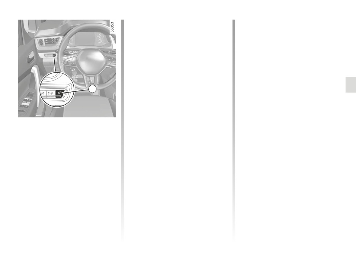
by pressing the switch 1 again.
Braking anticipation
Note: The function is reactivated auto-
Depending on the vehicle, when you
matically when the ignition is switched
rapidly release the accelerator, the
on or when a speed of approximately
system anticipates the braking ma-
30 mph (50 km/h) is exceeded.
noeuvre in order to reduce stopping
distances.
1
Emergency brake assist
Special cases
This system supplements the ABS
When using the cruise control:
and helps reduce vehicle stopping dis-
- if you use the accelerator, when you
tances.
release it, the system may be trig-
Disabling the traction control
Operating principle
gered;
system
The system is for detecting an emer-
- if you do not use the accelerator, the
gency braking situation. In this case,
system will not be triggered.
In some situations (driving on very wet
the braking system immediately devel-
ground: snow, mud, etc. or driving with
Operating faults
ops maximum power and may trigger
snow chains fitted), the system may
ABS regulation.
When the system detects an operating
reduce the engine output to limit wheel-
ABS braking is maintained as long as
fault the message “WARNING: Check
spin. If this is not required, it is possible
the brake pedal is applied.
Braking System” appears on the instru-
to deactivate the function by pressing
switch 1. In this case, the
warn-
ing light.
ing light appears continuously on the
Consult an approved dealer.
instrument panel accompanied by the
message “ESC OFF”. This action does
not deactivate the ESC.
2.45
DRIVING CORRECTION DEVICES AND AIDS (5/6)
Hill start assistance
Driver assistance with a
Depending on the gradient of the in-
trailer
cline, this system assists the driver
This system helps to maintain control
when starting on a hill. It prevents the
over the vehicle while using a trailer.
The hill start assistance
vehicle from rolling backwards by au-
It detects shaking caused by towing a
system cannot completely
tomatically applying the brakes when
trailer under certain driving conditions.
prevent the vehicle from
the driver lifts his/her foot off the brake
rolling backwards in all sit-
Operating conditions
pedal to depress the accelerator pedal.
uations (extremely steep gradients
- The towbar must be approved by an
etc.).
System operation
authorised dealer;
In all cases, the driver may depress
- the harness must be approved by an
It only operates when the gear lever is
the brake pedal to prevent the vehi-
authorised dealer;
in a position other than neutral (other
cle from rolling backwards.
- the towbar must be connected to the
than N or P for automatic transmis-
vehicle.
sions) and the vehicle is completely
The hill start assistance function
Operating principle
stationary (brake pedal depressed)
should not be used for prolonged
The function stabilises the vehicle by:
stops: use the brake pedal.
The system holds the vehicle for ap-
- asymmetric braking of the front
proximately 2 seconds. The brakes are
This function is not designed to im-
wheels to reduce shaking caused by
then gradually released (the vehicle will
mobilise the vehicle permanently.
the trailer;
move according to the slope).
- braking of all four wheels and limita-
If necessary, use the brake pedal to
tion on engine torque to reduce the
stop the vehicle.
vehicle speed until the shaking has
The driver must remain particularly
stopped.
vigilant when driving on slippery or
low-grip surfaces.
Warning light
flashes on the in-
strument panel to inform the driver.
Risk of serious injury.
2.46
DRIVING CORRECTION DEVICES AND AIDS (6/6)
Traction control - “Extended
“Soft ground” mode
grip"
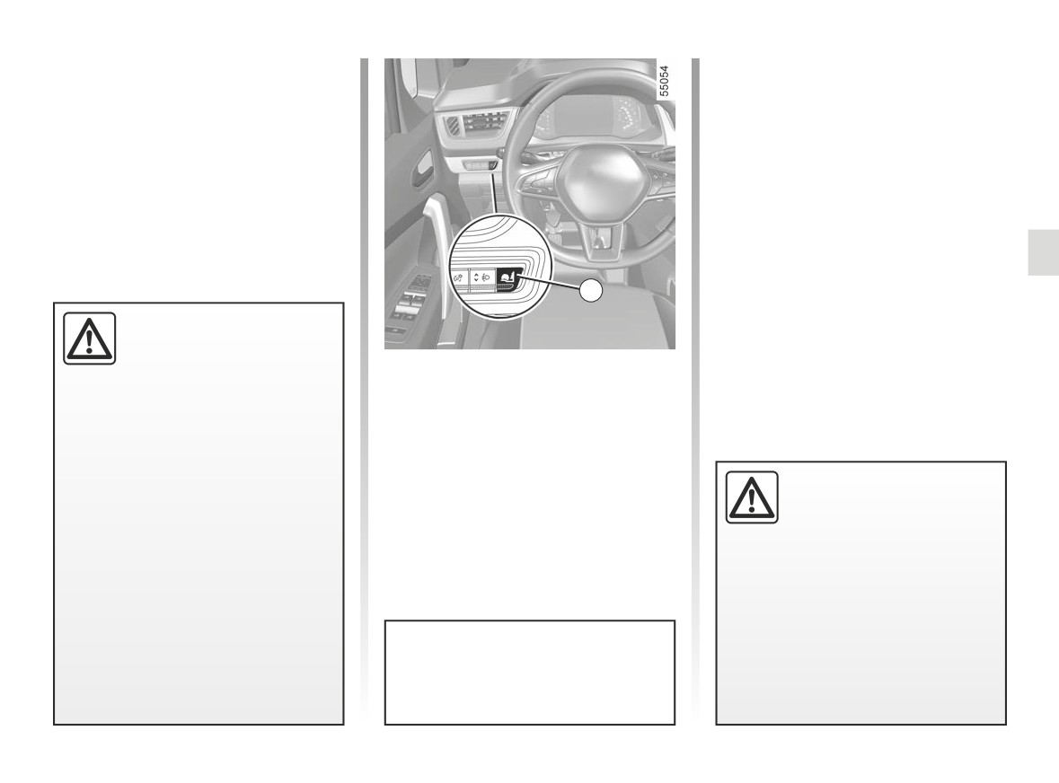
Press switch 2: the
warning
If fitted on the vehicle, grip control
light appears on the instrument panel
makes it easier to control the vehicle on
accompanied by the message “Grip
low grip surfaces (soft ground, etc.).
Extend Loose Surface ON”, followed by
the message “ESC OFF”. This position
enables optimal usage on soft ground
(mud, sand, dead leaves, etc.). In this
position, engine speed is left under the
driver’s control.
The system automatically switches to
2
“Road” mode at speeds above about
These functions are an ad-
31 mph (50 km/h). The
warn-
ditional aid in the event of
ing light disappears and the message
critical driving conditions,
“Standard road mode on” is displayed
“Road” mode
enabling the vehicle behav-
on the instrument panel to warn you.
When the vehicle starts, the message
iour to be adapted to suit the driving
“Standard road mode on” is displayed
conditions.
on the instrument panel.
The functions do not take the place
The default mode Road enables opti-
of the driver. They do not increase
mal use under normal road conditions
the vehicle’s limits and should
Tyres
(dry, wet, light snow, etc.).
not encourage you to drive more
When they need to be re-
“Road” mode uses traction control func-
quickly. Therefore, they can under
placed, only tyres of the
tions.
no circumstances replace the vigi-
same make, size, type and
lance or responsibility of the driver
profile should be used.
when manoeuvring the vehicle (the
Tyres fitted to the vehicle should
driver must always be ready for
either be identical to those fitted
sudden incidents which may occur
originally or conform to those
when driving).
recommended by your approved
dealer.
After the engine stops, the vehicle
will always restart in “Road” mode.
2.47
LANE DEPARTURE WARNING (1/5)
1
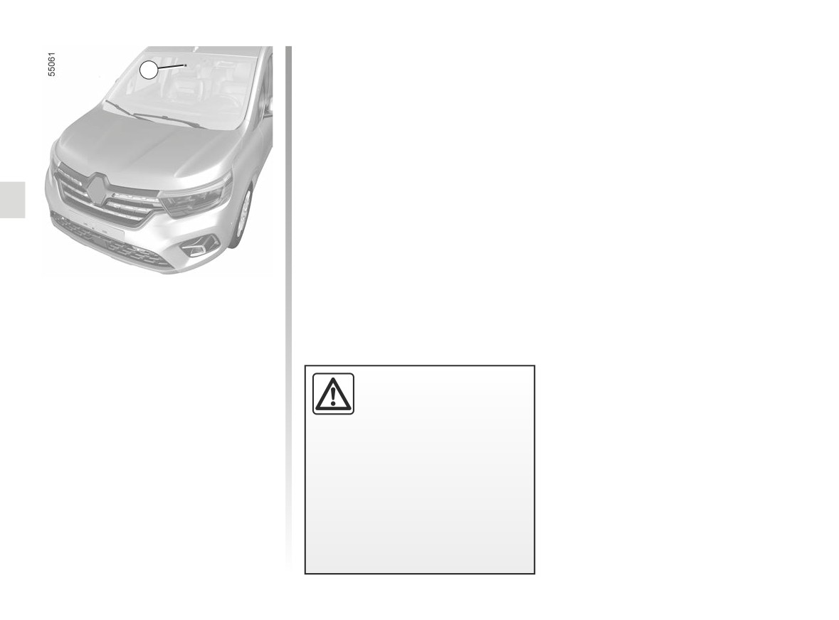
Using information from the camera 1,
the function warns the driver if they
cross a line (continuous or broken)
without the direction indicator light
being activated.
Note: make sure the windscreen is not
obscured (dirt, mud, snow, condensa-
This function is an addi-
tion etc.).
tional driving aid. This func-
tion is not under any cir-
cumstances intended to
replace the due care and attention
of the driver, who should at all times
be in control of the vehicle.
The lane departure warning func-
tion does not correct the vehi-
cle’s trajectory.
2.48
LANE DEPARTURE WARNING (2/5)
Operation
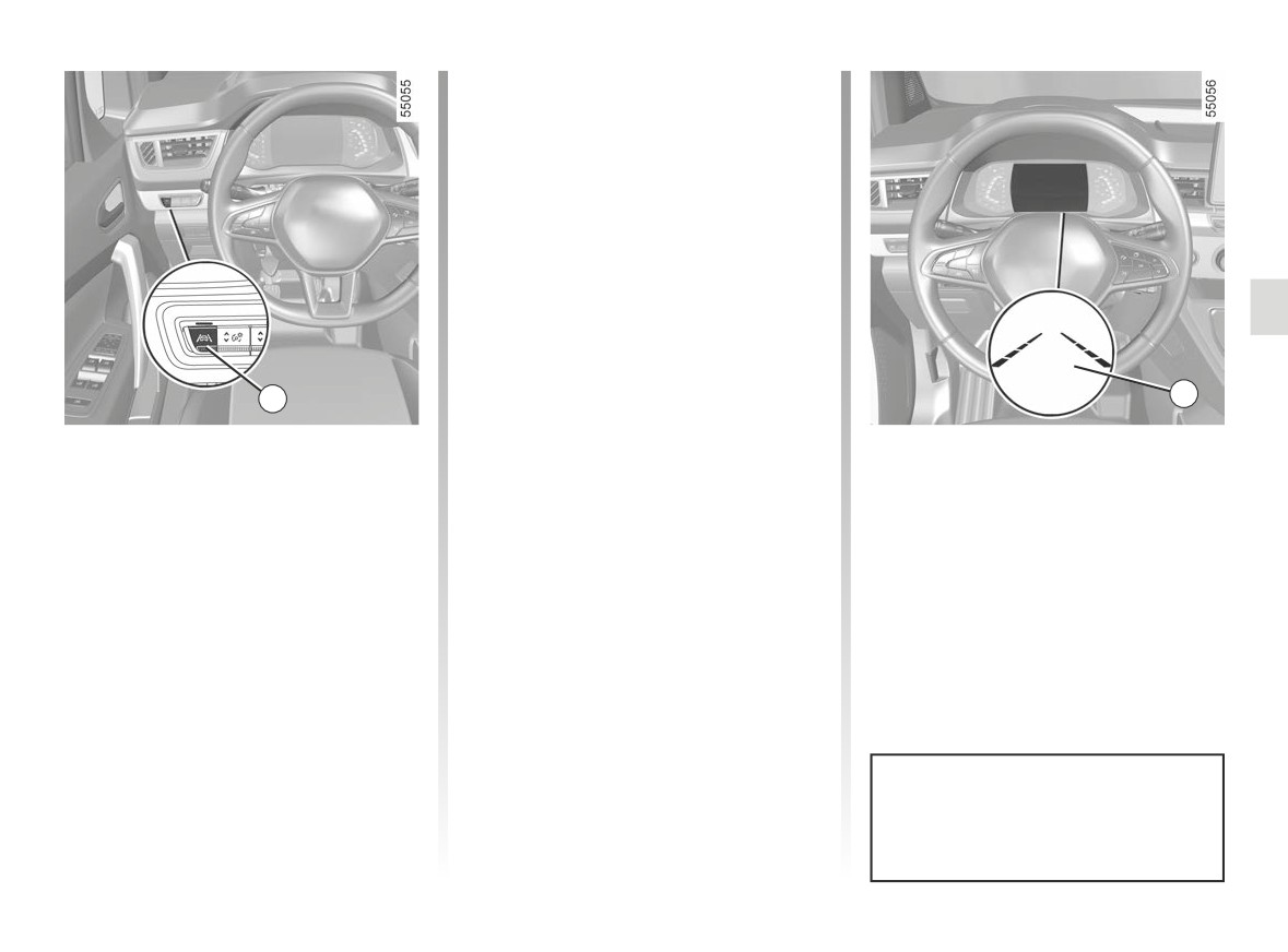
When the function is activated, the
warning light and the left and
right lines 3 are displayed in grey on the
instrument panel.
The function is set to notify the
driver if:
- speed is between approximately
43 mph (70 km/h) and 112 mph
(180 km/h);
and
- the
warning light and left/right
2
line indicators 3 are coloured white.
3
The function triggers an alert if a line
Activation/deactivation
The function alerts the driver:
is crossed without the direction indica-
To activate the function, press the 2
- by a vibration in the steering wheel;
tor being activated.
switch as many times as required to
and
select “Lane Departure Warning” on
- the
warning light and 3 the in-
the instrument panel. The “Lane depar-
dicator for the crossed line turn red.
ture warning on” message and “”
warning light are displayed on the in-
strument panel.
To disable the function, press the 2
switch as many times as required to
select
“Lane departure warning off”
(or, depending on the vehicle, “Lane
Keeping deactivated”) on the instru-
ment panel. Warning light
goes
Each time the vehicle is started,
out on the instrument panel.
the function continues the mode
saved the last time the engine was
stopped.
2.49
LANE DEPARTURE WARNING (3/5)
Temporarily not available
Conditions for non-activation
4
-
very fast lane departure;
of the system
The system cannot be activated when:
–
driving continuously on a line;
–
four seconds approximately after
- reverse gear is engaged;
changing lanes;
- the field of vision of the camera is ob-
-
tight bends;
structed;
–
impaired visibility;
- the û
warning light is displayed.
–
activating the direction indicator
lights;
The
warning light and the left/
right line indicators turn to grey on the
-
strong acceleration;
instrument panel.
-
changing the lane width;
–
operation of the active emergency
Adjustment
braking system;
-
“Alert”: adjust the line detection sen-
sitivity level. To do this select:
-
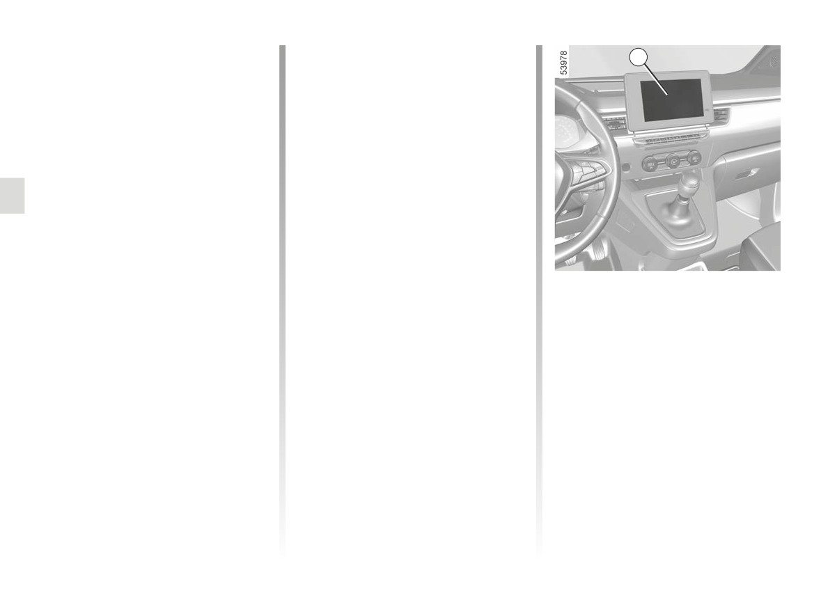
Vehicles fitted with a multimedia
screen.
- “At the latest”: line detected when
When the function is not available, the
crossing;
To access the multimedia screen func-
warning light and the left/right in-
tion settings 4, refer to the multimedia
- “Standard”: line detected on ap-
dicators turn to grey on the instrument
instructions:
proach;
panel.
- “VIBRATION”: adjust the steering
- “At the sooner”: line detected
wheel vibration level;
nearby.
Please refer to the multimedia instruc-
tions for further information.
2.50
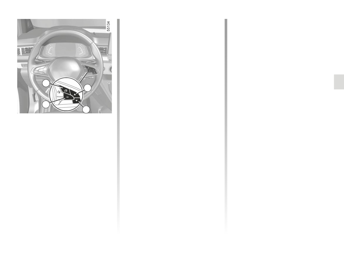
LANE DEPARTURE WARNING (4/5)
-
press control 6 or 7 repeatedly to
Operating faults
reach the DRIVING ASSIST menu.
In the event of a malfunction, the left
Press the switch 8 OK;
and right line indicators (and, depend-
-
scroll repeatedly by pressing con-
trol
6 or
7 to access the Lane
ing on display style, the
warning
Departure Warning sensitivity or
light) disappear or stay grey on the in-
Lane Departure Warning vibration
strument panel.
menu. Press the switch 8 OK;
In some cases, they are accompanied
-
press the 6 or 7 control repeatedly
by the message “Check Front camera”
to adjust the setting. Press the 8 OK
or the
warning light on the in-
5
button.
strument panel.
6
Consult an approved dealer.
8
7
Adjustments (continued)
Vehicles not fitted with a multimedia
screen
- With the vehicle stopped, press the
switch 5 as many times as required
to reach the “Vehicle” tab;
- press the 6 or 7 control repeatedly to
reach the “Settings” menu. Press the
switch 8 OK;
2.51
LANE DEPARTURE WARNING (5/5)
This function is an additional driving aid. This function is not under any circumstances intended to replace the due care
and attention of the driver, who should at all times be in control of the vehicle.
System servicing/repairs
- In the event of an impact, the camera alignment may be changed, and its operation may consequently be affected. Deactivate
the function, then consult an authorised dealer.
- Any work in the area where the camera is located (repairs, replacements, windscreen modifications etc.) must be carried
out by a qualified professional.
Only an authorised dealer is qualified to service the system.
In the event of system disturbance
Some conditions can disturb or damage the operation of the system, such as:
- windscreen obscured (by dirt, ice, snow, condensation etc.);
- a complex environment (tunnel etc.);
- poor weather conditions (snow, rain, hail, black ice etc.) ;
- poor visibility (night, fog etc.);
- the road markings are irregular or difficult to distinguish (e.g. partially erased, excessive spacing, distorted road surface) ;
- being dazzled (glaring sun, lights of vehicles travelling in the opposite direction etc.);
- the road is narrow, winding or undulating (tight bends etc.);
- closely following a vehicle travelling in the same lane.
Risk of false alarms or absence of warnings
2.52
LANE KEEPING ASSIST (1/6)
Note: make sure the windscreen is not
obscured (dirt, mud, snow, condensa-
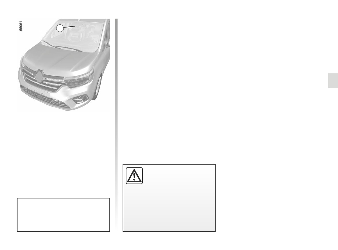
1
tion etc.).
Using information from the camera 1,
the function triggers a corrective action
on the vehicle steering system if a line
(continuous or broken) is crossed with-
out the direction indicator lights being
activated.
This function is an addi-
tional driving aid. This func-
tion is not under any circum-
stances intended to replace
the due care and attention of the
driver, who should at all times be
in control of the vehicle.
You can retake control of the ve-
hicle at any time by operating the
steering wheel.
2.53
LANE KEEPING ASSIST (2/6)
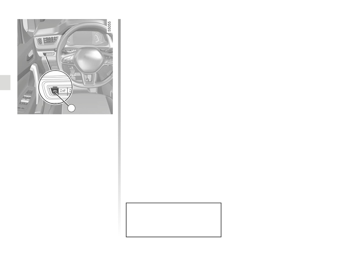
To disable the function, press the 2
switch as many times as required to
select “Lane Keeping deactivated” on
the instrument panel.
Warning light
goes out on the in-
strument panel.
Note: deactivating the “Lane Keeping
Assist” function causes deactivation of
the “Lane Departure Warning” function.
2
Activation/deactivation
To activate the function, press the 2
switch as many times as required to
select “Lane Keeping Assist” on the in-
strument panel.
The “Lane Keeping activated” message
and “
” warning light are displayed
on the instrument panel.
When Lane Keeping Assist is activated,
the “Lane Departure Warning” function
is automatically activated. ➥ 2.48.
Each time the vehicle is started,
the function continues the mode
saved the last time the engine was
stopped.
2.54
LANE KEEPING ASSIST (3/6)
In these cases:
Special cases
– the function triggers an action on the
When using the function:
vehicle’s steering system to correct
-
if the system no longer detects any
the vehicle trajectory;
action by the driver on the steering
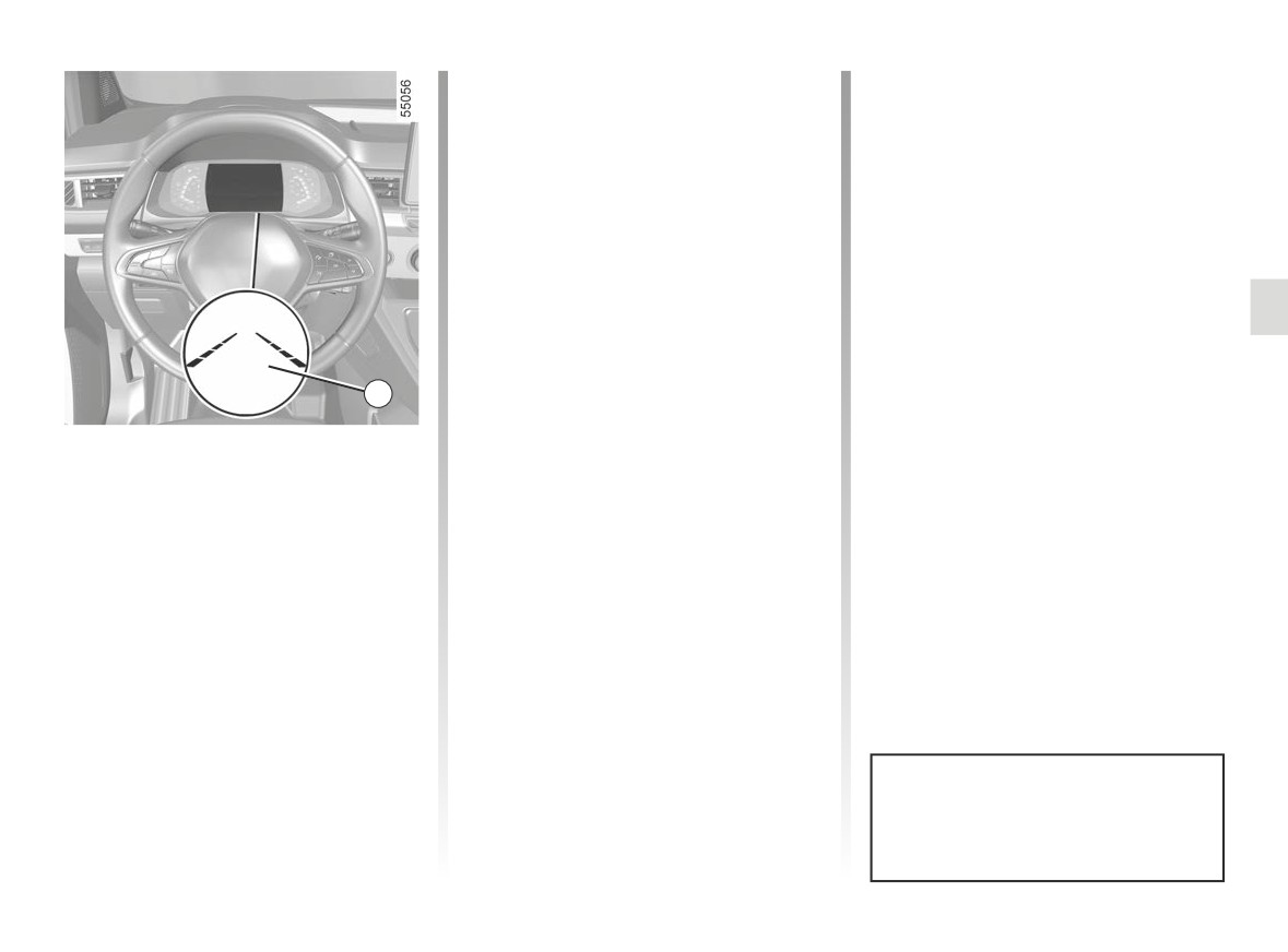
- the warning light
and the indi-
wheel, the
warning light ap-
cator 3 on the side of the breached
pears in yellow on the instrument
line turns to yellow on the instrument
panel, accompanied by the message
panel.
“Keep hands on steering wheel” and
an audible warning;
Note: on bends, the function allows for
slightly cutting the bend.
-
if the steering system corrective
action is active for too long, an au-
If the corrective action on the steer-
dible warning is emitted and the in-
3
ing system is not sufficient, the
dicator light 3 on the side of the line
warning light and 3 indicator on the side
concerned flashes until the driver
Operation
of the breached line turn to red on the
takes control.
When the function is activated, the
instrument panel, accompanied by a vi-
bration on the steering wheel.
warning light and the left and
right lines 3 are displayed in grey on the
instrument panel.
The function is set to operate when
the vehicle speed is between approxi-
mately 43 mph (70 km/h) and 112 mph
(180 km/h) and if the
warning
light and 3 correction indicators are col-
oured white.
The function is triggered if the vehi-
cle crosses a line without the direction
indicator lights being activated.
You can interrupt the trajectory cor-
rection at any time by moving the
steering wheel.
2.55