Renault Koleos (2018 year). Instruction - part 18
5.16
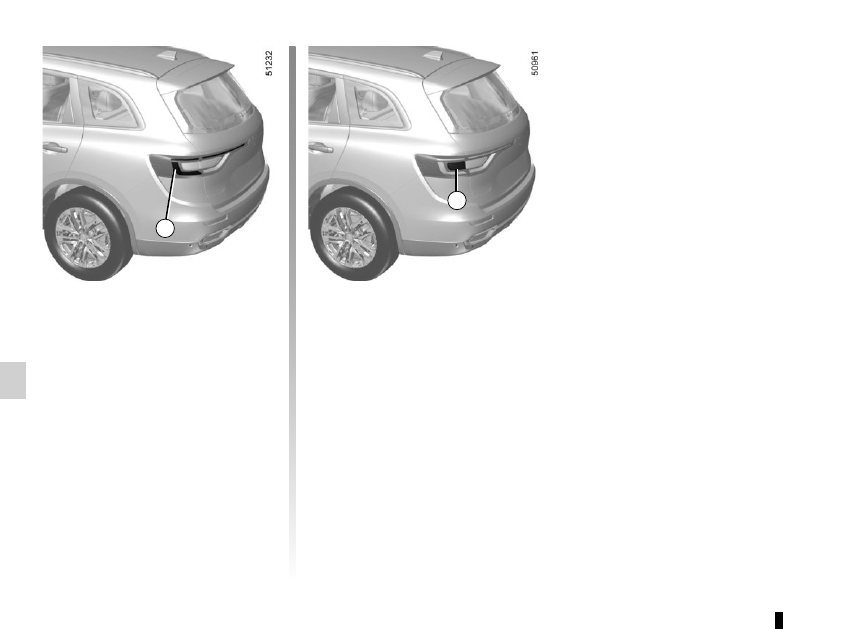
REAR AND SIDE LIGHTS: changing bulbs
(1/3)
Side lights and brake lights 1
Consult an approved Dealer.
1
Direction indicators 2
Consult an approved Dealer.
2
|
|
|
5.16 REAR AND SIDE LIGHTS: changing bulbs (1/3) Side lights and brake lights 1 Consult an approved Dealer. 1 Direction indicators 2 Consult an approved Dealer. 2 |