Renault Clio Sport Tourer (2016 year). Instruction - part 13
5.18
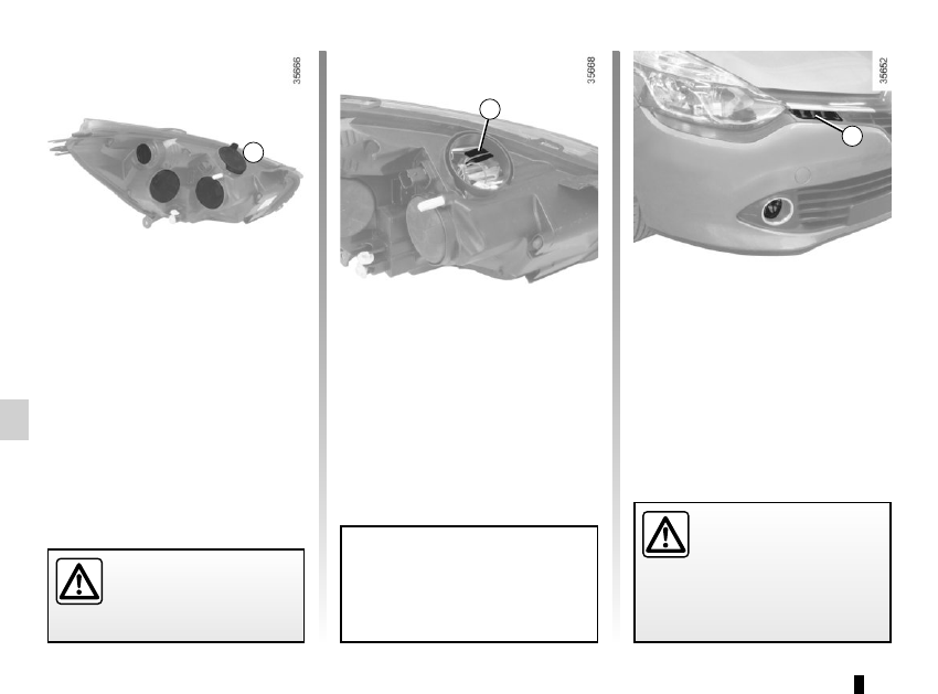
Front side light
(depending on the vehicle)
To change a bulb, remove cover A.
Pull bulb holder 6 to access the bulb.
Bulb type: W5W.
The engine may be hot
when carrying out opera-
tions in close proximity. In
addition, the engine cooling
fan can come on at any moment.
Risk of injury.
To comply with local legislation, or
as a precaution, you can obtain an
emergency kit containing a set of
spare bulbs and fuses from an ap-
proved dealer.
A
6
FRONT HEADLIGHTS: changing bulbs
(3/4)
7
Daytime running lights 7
(depending on the vehicle)
Please see an authorised dealer.
The bulbs are under pres-
sure and can break when
replaced.
Risk of injury.