Dacia SuperNova (engine E7J). Manual - part 11


  Index      Dacia     Dacia SuperNova (engine E7J) - service repair manual 2004 year


Search            


Content   ..  9  10  11  12   ..


Dacia SuperNova (engine E7J). Manual - part 11


ENGINE E7J-A-2/60

10

10 - 20

ENGINE AND LOWER ENGINE UNITS

D

ISMO UNTING

The following are to take off:

-the cylinder head cap;
-the intake and exhaust collectors;
-the cylinder head screws, except the

screw where the centring jack is; this one
is only loosened;

-the cylinder head is revolved round

the screw which was left in place;

-the cylinder head is taken off;
-the jacket-maintaining device -

MOT.484 - is mounted.

.

To be mounted:

-the rocker arm ramp:

-the oil-sealing of the cam-shaft;
-the flange of the cam-shaft;
-the pinion of  the cam-shaft, which is

blocked with MOT 799 - 01;

-the cam-shaft;
-the stand of the thermostat;
-the sparking plugs;
-the springs of the valves;
-the valves;
-the oil-seals of the valves, by using the

MOT. 1335 pincers.

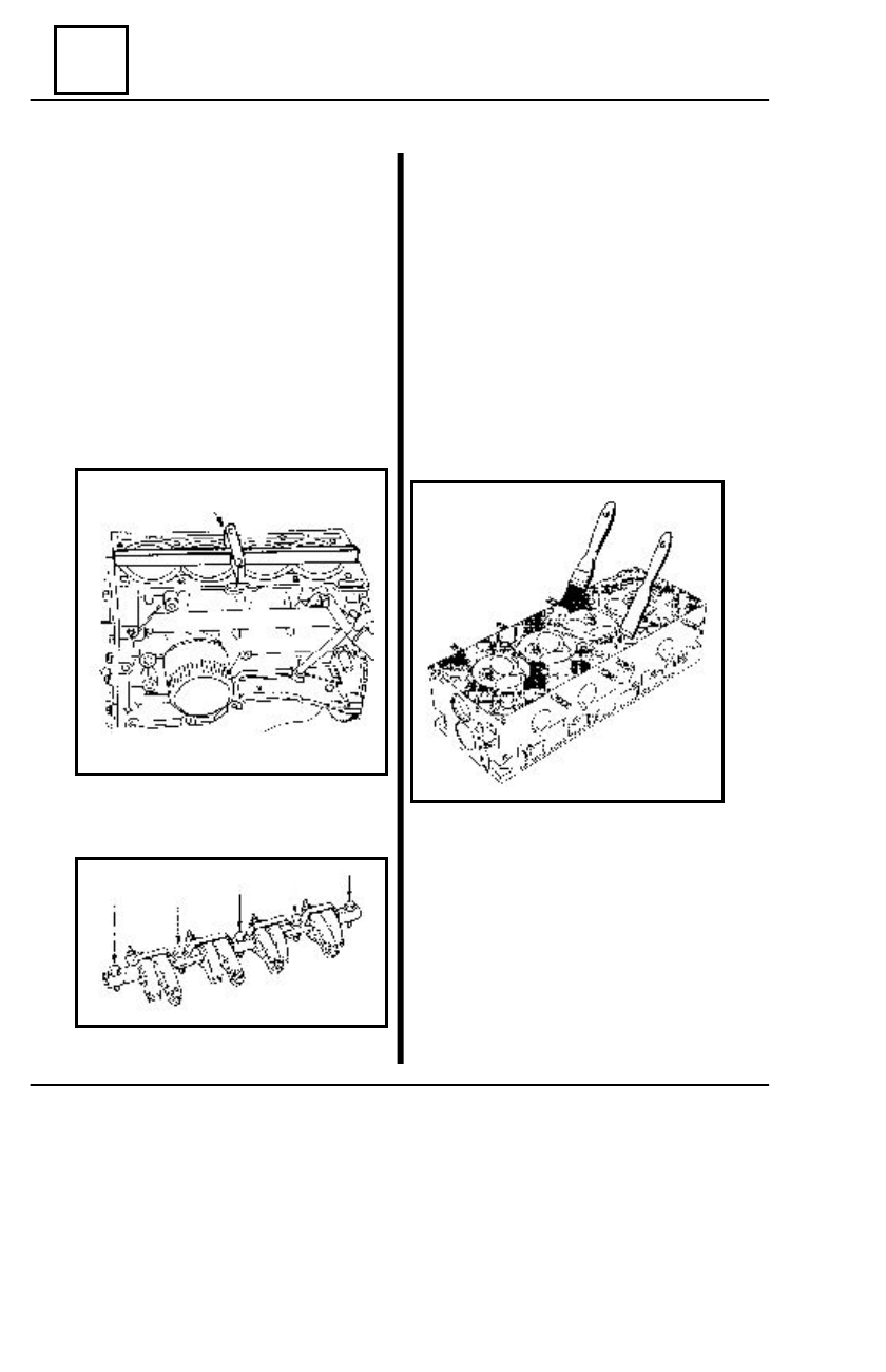
The cylinder head is cleaned of the fit-

ting which is left stuck to it.

It is very important not to get the po-

sitionin g surface of the fittings
scratched.

Use Decapjoint to remove the remains

of fittings that are left stuck.

The above product is applied on the

cleaning area; wait ca. 10 minutes, then
clean by means of a wooden spatula.

CYLINDER  HEAD

MOT. 484

RECOVERY ENGINE

ENGINE  E7J-A-2/60

10

10 - 21

ENGINE AND LOWER ENGINE UNITS

C

AUTION

!

Avoid introducing foreign bodies

into the oil grooves and  tubes; you may
risk blocking up the holes of  the rocker
arms and rapidly deteriorating the
cams and the gliding parts  of the
rocker-arms.

The checking of the planeness of the

cylinder head is to be done with a ruler
and a set of thickness gauges

Maximum distortion allowed:  0.05 mm.
No rectification of the combustion head

is authorized.

R

E

-M

O UNTING

Oil all the parts.
Mount the valve oil-seal rings no. 2 by

means of a tubular-wrench of 11 size onto
the valve guides no. 3;

Mount in the following order:

-the washers no. 1 at the base of the

valve springs;

-the new valves no. 4.

-the springs no.  5 are identical for

both intake and exhaust;

-caps no. 6;

Compress springs no. 5, then mount the

semi-cones no. 7, which are identical for
both intake and exhaust.

CYLINDER HEAD

C

AUTION

!

They must have the same line-up

marking (8) as the old ones in order
to avoid the destruction of the valve -
stool set.

RECOVERY ENGINE

ENGINE E7J-A-2/60

10

10 - 22

ENGINE AND LOWER ENGINE UNITS

 To mount:

  -camshaft annular oil seal by

means of the MOT 1127-01 device;

-the thermostat stand.

For watertight sealing, use Loctite 518.
Girdle H must be 0.6mm up to 1 mm

thick; it is applied in keeping with the fol-
lowing schema:

-the pinion of the cam-shaft is fixed

with the MOT 799-01  device, then the
thread and the end of the screw are oiled
and the screw is tightened at 4.5 daNm.

CYLINDER HEAD

R

E

-M

O UNTING

Oil the cam-shaft.
Mount the cam-shaft and its flange.
Check the axial play, which has to be

within 0.06 mm and 0.15 mm; in case it
does not fit, check the flange or the cam-
shaft.

RECOVERY ENGINE

ENGINE  E7J-A-2/60

10

10 - 23

ENGINE AND LOWER ENGINE UNITS

 THE CYLINDER CRANKCASE

RECOVERY ENGINE


Content   ..  9  10  11  12   ..