Renault Scenic 3 Chassis. Manual - part 49


  Index      Renault     Renault Scenic 3 Chassis - Manual


Search            


Content   ..  47  48  49  50   ..


Renault Scenic 3 Chassis. Manual - part 49


38C

-

9

ANTI-LOCK BRAKING SYSTEM

Hydraulic unit

K4M

38C

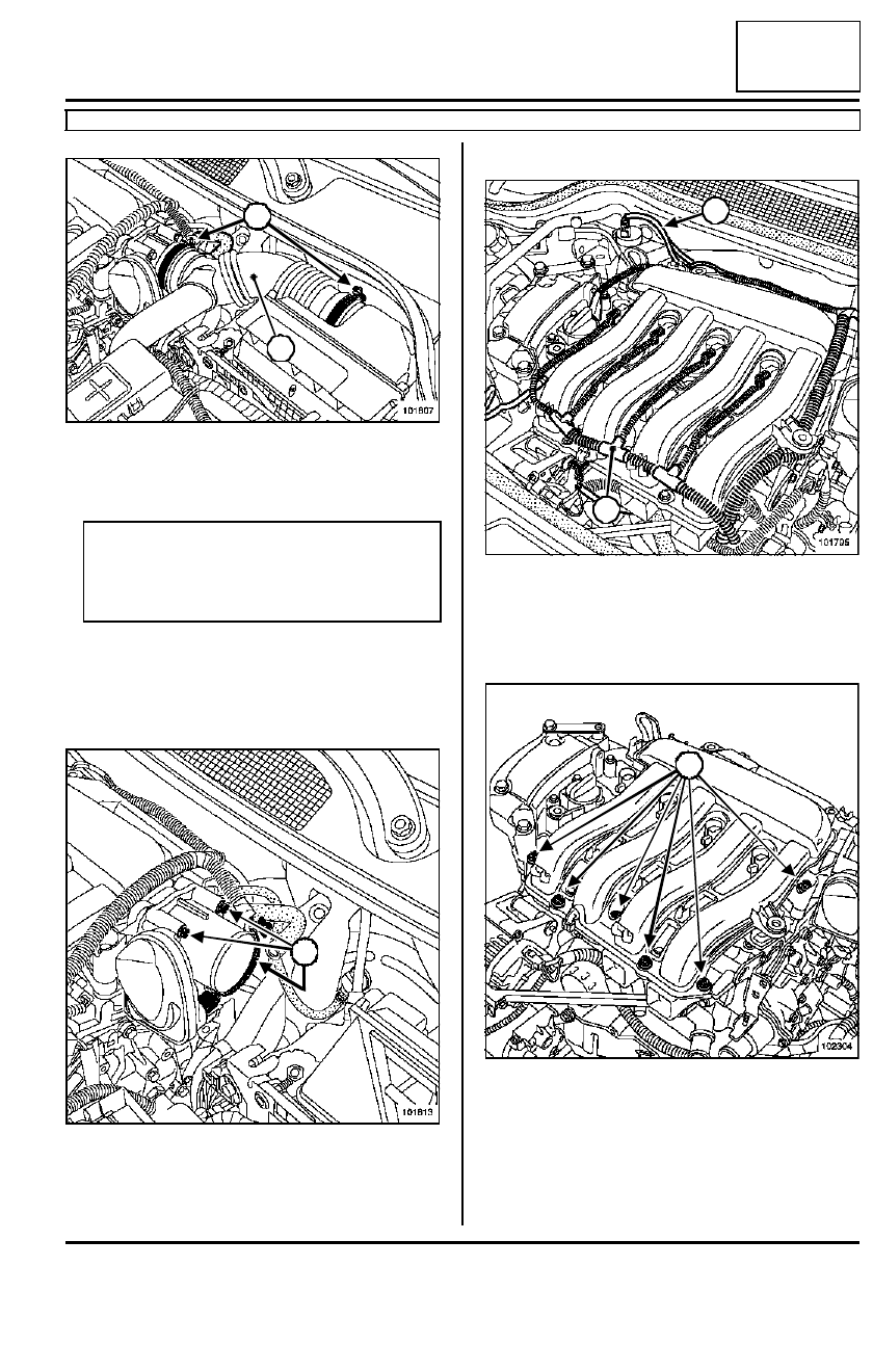
Loosen the air duct clips (4).

Remove the air duct (5).

Disconnect:

- the brake servo vacuum pipe at the air distributor

end,

- the ignition coil connectors.

Disconnect the throttle valve connector.

Remove:

- the throttle valve mounting bolts (6),

- the throttle valve.

Unclip the petrol vapour recirculation pipe (8).

Disconnect the air temperature sensor.

Remove the engine wiring harness (7).

Remove:

- the air distribution unit mounting bolts (9),

- the air distribution unit,

- the soundproofing screen mountings.

Remove the soundproofing screen.

101807

Note:

Do not damage the vacuum outlet on the air dis-
tributor. If it is damaged, the air distributor will
have to be replaced.

101813

5

4

6

6

101795

102304

8

7

9

9

9

38C

-

10

ANTI-LOCK BRAKING SYSTEM

Hydraulic unit

K4M

38C

Remove the lifting eye (10).

Remove the air conditioning pipe (see Evaporator -
dehydration canister
).

Remove the ABS computer earth terminal mounting
bolt. 

Disconnect the computer connector.

Unscrew the six hydraulic unit pipes.

Unclip the six pipes from the hydraulic unit.

Remove:

- the hydraulic unit support mounting bolts (11),

- the « hydraulic unit - support » assembly,

- the hydraulic unit.

REFITTING

Proceed in the reverse order to removal.

104324

AIR CONDITIONING or CLIMATE CONTROL

10

104341

WARNING

- Replace the throttle valve seal each time it is

removed.

- Position the hydraulic unit earth ter minal wire

facing downwards to optimise the computer
connector sealing.

11

11

38C

-

11

ANTI-LOCK BRAKING SYSTEM

Hydraulic unit

K4M

38C

Refit the air conditioning pipe (see Evaporator - de-
hydration canister
).

Torque tighten:

- the hydraulic unit support mounting bolts   (0.65

daNm),

- the hydraulic unit - support mounting bolts (0.8

daNm),

- the  bolts securing the pipes on the hydraulic

unit (1.4 daNm),

- the air distributor mounting bolts (0.9 daNm).

Bleed the braking circuit using the Diagnostic tool

(Section General Vehicle Information, Braking circuit
bleed,  page 30A-5).

Fill up the refrigerant circuit using the filling station
tool.

106032

WARNING

Set up the earth terminal wires facing
downwards, to optimise the hydraulic unit compu-
ter connector sealing.

AIR CONDITIONING or CLIMATE CONTROL

WARNING

- When the ignition is switched on, the throttle

valve should run a minimum and maximum stop
programming cycle. Using the Diagnostic tool,
check that this programming has been executed
correctly.

- Connect the battery; carry out the necessary

programming (Section Electrical equipment).

AIR CONDITIONING or CLIMATE CONTROL

Note:

- Make sure that the air conditioning is working

properly  with the fan assembly at maximum
speed.

- If  there is no cold air flow, look for leaks (see

Leak detection).

38C

-

12

ANTI-LOCK BRAKING SYSTEM

Hydraulic unit

F9Q or K9K

38C

REMOVAL

Disconnect the battery, starting with the negative ter-
minal.

Fit a pedal press tool to the brake pedal to restrict
the outflow of brake fluid.

Drain the refrigerant circuit using the filling station
tool.

Remove the cowl grille (see  Wiping - WashingSec-
tion).

Remove:

- the engine covers,

- the two air filter access panel mounting bolts (1)

- the plenum chamber partition mounting bolts (2),

- the plenum chamber partition.

Remove the plenum chamber bracket (3).

Equipment required

pedal press

filling station

Diagnostic tool

Tightening torques

m

hydraulic unit support
mounting bolts

0.65 daNm

hydraulic unit - support
mounting bolts

0.8 daNm

bolts securing the pipes
on the hydraulic unit

1.4 daNm

AIR CONDITIONING or CLIMATE CONTROL

104343

104246

104666

2

1

2

2

3


Content   ..  47  48  49  50   ..