Renault Scenic 3 Chassis. Manual - part 39
37A
-
47
MECHANICAL COMPONENT CONTROLS
Clutch pedal
RIGHT-HAND DRIVE
37A
REMOVAL
Disconnect the battery starting with the negative ter-
minal.
Drain the brake fluid reservoir until the level is below
the master supply port.
Remove:
- the engine covers,
- the scuttle panel grille ( Wiping - WashingSec-
tion),
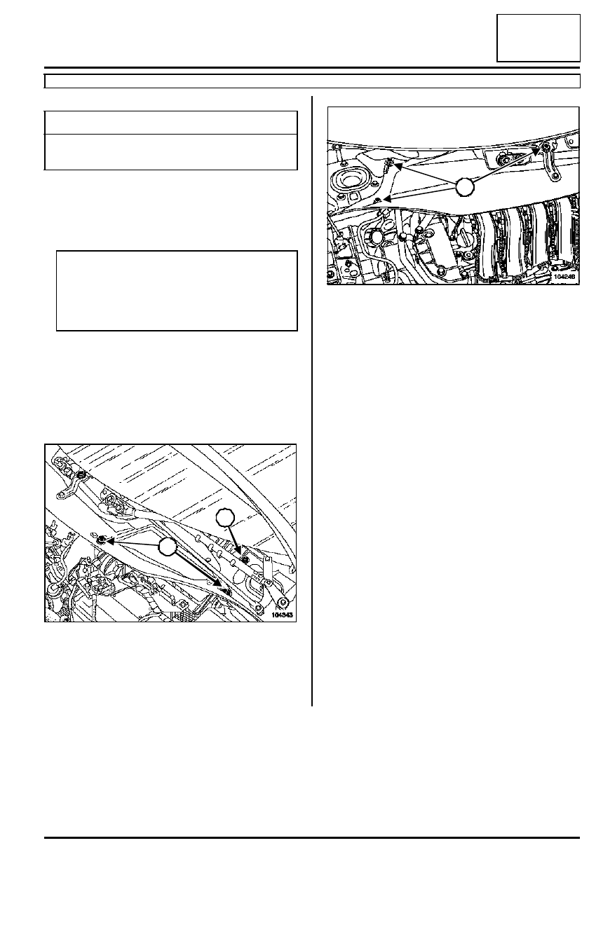
Remove:
- both air filter access flap mounting bolts (1),
- the air filter access flap,
- the radiator tank partition mounting bolt (2).
Remove:
- the radiator tank partition mounting bolts (3),
- the radiator tank partition panel.
Remove:
- the battery,
- the battery tray,
- the computer with its mounting,
- the air filter outlet duct.
Drain the brake fluid reservoir until the level is below
the master supply port.
Tightening torques
m
clutch pedal plate to tor-
que
2.1 daNm
Note:
The clutch master cylinder is secured to the
clutch pedal assembly. Remove the «
pedal
assembly /master cylinder » unit to remove the
pedals or the master cylinder.
104343
2
1
104246
3
3