Renault Scenic 3 Chassis. Manual - part 6
30A
-
17
GENERAL VEHICLE INFORMATION
Values and adjustments for the rear axle assemblies
30A
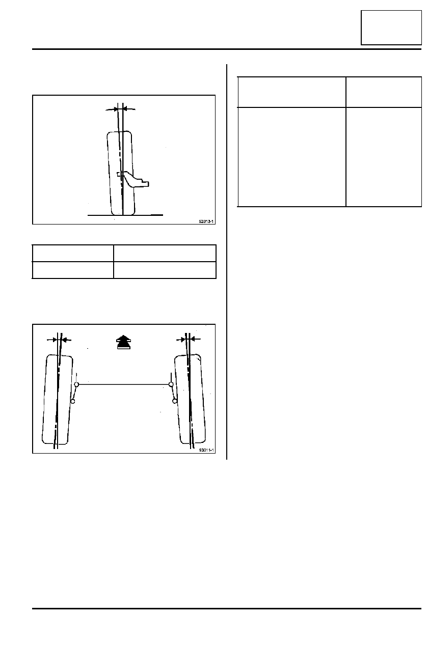
I - CAMBER
Not adjustable.
II - WHEEL ALIGNMENT
Not adjustable.
III - POSITION FOR TIGHTENING RUBBER BUSHES
To tighten rubber bushes, (see 33A, Rear Lifting com-
ponents, Tighten in axle position).
93013-1
Values
Position of rear axle
- 1˚ 30’
±
20’
Unladen
93011-1
Values
Position of axle
REAR
(For two wheels)
Toe-in: + 0˚ 35’
±
20’
15-inch wheel rim: -3.9 mm
±
2.3 mm
16-inch wheel rim: -4.2 mm
±
2.4 mm
17-inch wheel rim: -4.4 mm
±
2.6 mm
Unladen