Peugeot 308 SW BL (2013 year). Instruction - part 13
 

  Index      Peugeot     Peugeot 308 SW BL - instruction 2013 year in english


Search            


Content   ..  11  12  13  14   ..


Peugeot 308 SW BL (2013 year). Instruction - part 13


11

191

PRACTICAL INFORMATION

  Tyre under-infl ation detection 
 The spare wheel is not fi tted with a 

sensor. The punctured wheel must 

be repaired by a PEUGEOT dealer 

or a qualifi ed workshop. 

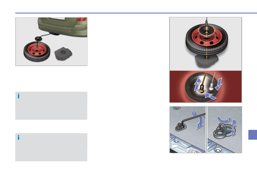
  Putting the wheel back in place 
   )   Store tools  2  and  3  in the box and 

close the cover. 

  )   Position the box on the ground. 
  )   Place the spare wheel on the box. 
  )   Fit the black plastic centring cone in 

the centre of the wheel (on steel or 

"space-saver" type wheels only). 

  )  Pass the hooking device through 

the cone and the wheel to secure it 

to the box cover. 

  )   Raise the wheel/box assembly un-

derneath the rear of the vehicle by 

tightening the winch control nut us-

ing the wheelbrace  1 . 

  )   Fully tighten the nut. 
  )  Close the fl ap with the eyelet and 

cover to secure the winch. 

  )  Check that the wheel is located 

squarely against the fl oor.   


If not, repeat the operation.    

 If you purchase a wheel of standard 

size to replace the "space-saver" 

type spare wheel, the spacer, lo-

cated underneath the vehicle, must 

be removed. Contact a PEUGEOT 

dealer or a qualifi ed workshop.  

11

192

PRACTICAL INFORMATION

  Parking the vehicle 
 Immobilise the vehicle where it 

does not block traffi c: the ground 

must be level, stable and non-slip-

pery ground. 
 Apply the parking brake, switch off 

the ignition and engage fi rst  gear *  

to lock the wheels. 
 If necessary, place a chock under 

the wheel diagonally opposite the 

wheel to be changed. 
 It is imperative that you ensure that 

the occupants get out of the vehicle 

and wait where they are safe. 
 Never go underneath a vehicle 

raised using a jack; use an axle 

stand.  

          Removing the wheel 

  List of operations 
   )  Remove the fi nisher cap from each 

wheel bolt using tool  3 . 

  )   Fit the security socket  4  on the wheel-

brace  1  to slacken the security bolt. 

  )  Slacken the other bolts using the 

wheelbrace  1  only. 

  )   Place the jack  2  in contact with one 

of the two front  A  or rear  B  locations 

provided on the underbody, which-

ever is closest to the wheel to be 

changed. 

  )   Extend the jack  2  until its base plate 

is in contact with the ground. Ensure 

that the centreline of the jack base 

plate is directly below the location  A  

or  B  used. 

  )   Raise the vehicle until there is suf-

fi cient space between the wheel and 

the ground to admit the spare (not 

punctured) wheel easily. 

  )   Remove the bolts and store them in 

a clean place. 

  )   Remove the wheel.    

  *    position  R  for the electronic gear 

control gearbox;  

P  for the auto-

matic gearbox.  

11

193

PRACTICAL INFORMATION

  After changing a wheel 
 To store the punctured wheel in the 

boot correctly, fi rst remove the cen-

tral cover. 
 When using the "space-saver" type 

spare wheel, do not exceed 50 mph 

(80 km/h). 
 Have the tightening of the bolts and 

the pressure of the spare wheel 

checked by a PEUGEOT dealer or 

a qualifi ed workshop without delay. 
 Have the punctured wheel repaired 

and replace it on the vehicle as 

soon as possible.  

  Fitting the wheel 

  List of operations 
   )   Put the wheel in place on the hub. 
  )   Screw in the bolts by hand to the 

stop. 

  )   Pre-tighten the security bolt using the 

wheelbrace  1  fi tted with the security 

socket  4 . 

  )   Pre-tighten the other bolts using the 

wheelbrace  1  only. 

  )   Lower the vehicle fully. 
  )   Fold the jack  2  and detach it. 

  )   Tighten the security bolt using the 

wheelbrace  1  fi tted with the security 

socket  4 . 

  )  Tighten the other bolts using the 

wheelbrace  1  only. 

  )  Refi t the fi nisher caps on each wheel 

bolt. 

  )   Store the tools in the box.    

11

194

PRACTICAL INFORMATION

  Risk of electrocution 
 Xenon bulbs (D1S-35W) must be 

replaced by a PEUGEOT dealer or 

a qualifi ed workshop.   

CHANGING A BULB

        Model with halogen headlamps 

   1.    Direction indicators 

(PY21W amber).  

  2.    Dipped beam headlamps 

(H7 - 55W).  

  3.    Main beam headlamps 

(H1 - 55W).  

  4.    Daytime running lamps / 

sidelamps (P21/5W)    

 or 


 Daytime running lamps / 

sidelamps (LEDs).  

  5.    Foglamps (H8 - 35W).     

   1.    Direction indicators 

(PY21W SV silver).  

  2.    Directional dipped / main beam 

headlamps (D1S-35W).  

  3.    Additional main beam headlamps 

(H1-55W).  

  4.    Daytime running lamps / sidelamps  

 (P21/5W)    

 or 


 Daytime running lamps / sidelamps 

(LEDs).  

  5.    Foglamps (H8-35W).    

                             Model with xenon and directional 

headlamps 

 The headlamps are fi tted with poly-

carbonate glass with a protective 

coating: 
   )    do not clean them using a dry 

or abrasive cloth, nor with a 

detergent or solvent product,  

  )   use a sponge and soapy water, 
  )  when using a high pressure 

washer on persistent marks, do 

not keep the lance directed to-

wards the lamps or their edges 

for too long, so as not to dam-

age their protective coating and 

seals, 

  )   do not touch the bulb directly 

with your fi ngers, use lint-free 

cloths.  

  Changing a bulb should only be 

done after the headlamp has been 

switched off for a few minutes (risk 

of serious burns). 
 It is imperative to use only anti-ultra-

violet (UV) type bulbs in order not to 

damage the headlamp. 
 Always replace a failed bulb with a 

new bulb with the same type and 

specifi cation.  

  Front lamps  

11

195

PRACTICAL INFORMATION

                 Changing main beam headlamp 

bulbs 
   )  Remove the protective cover by 

pulling the tab. 

  )   Disconnect the bulb connector. 
  )   Compress the springs to release the 

bulb. 

  )   Extract the bulb and change it.  
 To refi t, carry out these operations in re-

verse order.  

  Changing daytime running lamp / 

sidelamp bulbs 
   )  Remove the protective cover by 

pulling the tab. 

  )   Disconnect the bulb connector. 
  )   Turn the bulb holder a quarter of a 

turn and extract it. 

  )   Pull the bulb out and change it.  
 To refi t, carry out these operations in re-

verse order.  

        Changing dipped beam headlamp 

bulbs 
   )  Remove the protective cover by 

pulling the tab. 

  )   Disconnect the bulb connector. 
  )   Spread the springs to release the 

bulb. 

  )   Pull the bulb out and change it.  
 To refi t, carry out these operations in re-

verse order.   

   Changing direction indicator bulbs 

   )   Turn the bulb holder a quarter of a 

turn and extract it. 

  )   Pull the bulb out and change it.  
 To refi t, carry out these operations in re-

verse order. 

 Amber or silver coloured bulbs, 

such as the direction indicators, 

must be replaced with bulbs of 

identical specifi cations and colour.

  When refi tting, close the protective 

cover carefully to assure the seal-

ing of the headlamp.   

11

PRACTICAL INFORMATION

        Changing front foglamp bulbs 

   )   Insert a screwdriver at the middle of 

the repeater between the repeater 

and the base of the mirror. 

  )   Tilt the screwdriver to extract the re-

peater and remove it. 

  )   Disconnect the repeater connector.  
 To refi t, carry out these operations in re-

verse order. 
 Contact a PEUGEOT dealer or a quali-

fi ed workshop to obtain replacement re-

peaters.   

  Changing integrated direction 

indicator side repeaters 

 To replace these bulbs contact a PEUGEOT 

dealer or a qualifi ed workshop.   

   Changing the daytime running 

lamps / sidelamps  

 For the replacement of this type of LED 

lamp, contact a PEUGEOT dealer or a 

qualifi ed workshop.  

11

197

PRACTICAL INFORMATION

                                  Rear lamps 

   1.    Brake lamps / sidelamps (P21/5W).  
  2.    Sidelamps (P21/5W).  
  3.    Foglamp, offside (P21W).    
 

 Reversing lamp, nearside (P21W).  

  4.    Direction indicators (P21W).   

  Changing bulbs 
 These fi ve bulbs are changed from out-

side the boot: 

  )   remove the two lamp fi xing nuts, 
  )   extract the lamp carefully from the 

outside, 

  )   disconnect the lamp connector, 

  )   press the four tabs and remove the 

bulb holder, 

  )   turn the bulb a quarter of a turn and 

change it.  

 To refi t, carry out these operations in re-

verse order.  

 If the vehicle is fi tted with the JBL 

audio system, on the right-hand 

side,  fi rst remove the three fi xing 

bolts, then move the box. 

   )   on the right-hand side; remove the 

access fl ap, 

  )   on the left-hand side; turn the fi xing 

bolt a quarter of a turn and remove 

the storage box cover, 

  )   unclip the storage box, 

11

198

PRACTICAL INFORMATION

  Changing third brake lamp bulbs 

(4 bulbs W5W) 

   )   Unclip the tailgate upper trim from 

left to right. 

  )   Unscrew the two lamp fi xing nuts  A . 
  )   Unclip the lamp's central pin. 
  )   Extract the lamp from the outside. 
  )   Disconnect the bulb holder connector 

and the wash-wipe pipe. 

  )   Unclip the bulb holder from the lamp 

by pressing on the two tabs  B . 

  )   Pull the bulb and change it.  
 To refi t, carry out these operations in re-

verse order. 
 Do not apply force to the lamp when 

tightening the nuts.  

  Changing the number plate lamp 

bulbs (W5W) 

   )   Insert a thin screwdriver into one of 

the outer holes of the lens. 

  )   Push it outwards to unclip. 
  )   Remove the lens. 
  )   Pull the bulb and change it.    

11

199

PRACTICAL INFORMATION

                               Rear lamps 

   1.    Brake lamps / sidelamps (P21/5W).  
  2.    Sidelamps (P21/5W).  
  3.    Foglamp, offside (P21W)    
 

 Reversing lamp, nearside (P21W).  

  4.    Direction indicators (P21W)   

  Changing bulbs 
 These fi ve bulbs are changed from out-

side the boot: 

  )   unclip the lamp connector, 
  )  separate the fi ve tabs and remove 

the bulb holder, 

  )   turn the bulb a quarter of a turn and 

change it.  

   )   open the boot, 
  )   unscrew the two lamp fi xing bolts, 
  )   extract the lamp carefully pulling it 

from the bottom and pivoting it to-

wards the outside, 

 To refi t, carry out these operations in re-

verse order. 
 Take care to engage the lamp in its 

guides keeping it in line with the vehicle.  

11

PRACTICAL INFORMATION

  Changing the number plate lamp 

bulbs (W5W) 

   )   Insert a thin screwdriver into one of 

the outer holes of the lens. 

  )   Push it outwards to unclip. 
  )   Remove the lens. 
  )   Pull the bulb and change it.    

                 Changing the third brake lamp 

(SW - 4 bulbs W5W) 

   )   Remove the two lamp fi xing nuts  A . 
  )   Take out the lamp from the outside. 
  )   Disconnect the connector and the 

screenwash pipe from the lamp. 

  )   Turn the bulb holder corresponding 

to the faulty bulb a quarter of a turn. 

  )   Pull the bulb and change it.  
 To refi t, carry out these operations in re-

verse order. 
 Do not force the lamp when tightening 

the nuts.   

   Changing the third brake lamp 

(SW - LEDs) 

 For the replacement of this type of LED 

lamp, contact a PEUGEOT dealer or a 

qualifi ed workshop.   

11

201

PRACTICAL INFORMATION

  PEUGEOT will not accept responsi-

bility for the cost incurred in repairing 

your vehicle or for rectifying mal-

functions resulting from the installa-

tion of accessories not supplied and 

not recommended by PEUGEOT 

and not installed in accordance with 

its instructions, in particular when 

the combined consumption of all of 

the additional equipment connected 

exceeds 10 milliamperes.   

  Installing electrical accessories 
 Your vehicle's electrical system is 

designed to operate with standard 

or optional equipment. 
 Before installing other electrical 

equipment or accessories on your 

vehicle, contact a PEUGEOT dealer 

or a qualifi ed workshop.  

CHANGING A FUSE 

  Access to the tools 

 The extraction tweezer is fi tted on the 

back of the dashboard fusebox cover. 
 To gain access to it: 
   )   turn the screw a quarter of a turn to 

the left, 

  )   unclip the cover by pulling the top 

right, 

  )  remove the cover completely and 

turn it over, 

  )   remove the carrier, on the back of 

which is fi tted the tweezer.   

  Changing a fuse 

 Before changing a fuse: 
   )  the cause of the failure must be 

identifi ed and rectifi ed, 

  )  all electric consumers must be 

switched off, 

  )  the vehicle must be immobilised 

with the ignition off, 

  )   identify the failed fuse using the al-

location tables and drawings in the 

following pages.  

 To replace a fuse, you must: 
   )   use the special tweezer to extract 

the fuse from its housing and check 

its fi lament, 

  )   always replace the failed fuse with 

a fuse of the same rating (same col-

our); use of a different rating may 

cause malfunctions (risk of fi re).  

 If the fault recurs soon after changing 

the fuse, have the electrical system 

checked by a PEUGEOT dealer or a 

qualifi ed workshop. 

  Good  

  Failed  

  Tweezer  

11

202

PRACTICAL INFORMATION

  Dashboard fuses 

 The fusebox is placed in the lower section 

of the dashboard (left-hand side). 

  Access to the fuses 
   )   refer to the paragraph "Access to 

the tools".   

  Fuse tables 

   Fuse N°   

   Rating   

  Functions  

   F1   

   15 A   

 Rear wiper. 

   F2   

   30 A   

 Locking and deadlocking earth. 

   F3   

   5 A   

 Airbags and pretensioners control unit. 

   F4   

   10 A   

 Clutch pedal and dual-function brake switches, 

electrochromatic rear view mirror, air conditioning, 

steering wheel angle sensor, automatic gearbox, 

switching and protection unit. 

   F5   

   30 A   

 Front one-touch electric windows, folding mirrors 

supply, panoramic sunroof blind. 

   F6   

   30 A   

 Rear one-touch electric windows, trailer fusebox. 

   F7   

   5 A   

 Front and rear courtesy lamps, map reading lamps, 

rear reading lamps, sun visor illumination, glove 

box illumination, torch. 

   F8   

   20 A   

 Audio equipment, audio/telephone, multifunction 

screen, tyre under-infl ation detection. 

   F9   

   30 A   

 Front 12 V socket. 

   F10   

   15 A   

 Steering mounted controls, alarm siren, alarm 

control unit. 

   F11   

   15 A   

 Low current ignition switch. 

11

203

PRACTICAL INFORMATION

   Fuse N°   

   Rating   

  Functions  

   F12   

   15 A   

 Instrument panel, seat belt and passenger's front 

airbag warning lamps display, air conditioning, 

driver's seat memory unit, 2nd row rear seat 

switches, driving school module. 

   F13   

   5 A   

 Engine fusebox, airbags, electronic gear control 

gearbox gear lever, trailer fusebox. 

   F14   

   15 A   

 Multifunction screen, amplifi er, Bluetooth system, 

rain / sunshine sensor, parking sensors control unit. 

   F15   

   30 A   

 Locking and deadlocking. 

   F17   

   40 A   

 Rear screen and door mirrors demist/defrost. 

   SH   

   -   

 PARC shunt. 

   Fuse N°   

   Rating   

  Functions  

   G36   

   30 A   

 Driver and passenger heated seats. 

   G37   

   5 A   

 Driving position memory unit, lighting dimmer. 

   G38   

   30 A   

 Driver's seat memory unit. 

   G39   

   30 A   

 Trailer fusebox supply. 

   G40   

   30 A   

 Hi-Fi amplifi er. 

11

204

PRACTICAL INFORMATION

  Engine compartment fuses 

 The fusebox is placed in the engine 

compartment near the battery (left-hand 

side). 

   Fuse N°   

   Rating   

  Functions  

   F1   

   20 A   

 Engine control unit supply, injection pump and EGR 

electrovalves (2 litre HDI), injectors (2 litre HDI). 

   F2   

   15 A   

 Horn. 

   F3   

   10 A   

 Front / rear wash-wipe. 

   F4   

   20 A   

 Headlamp wash. 

   F5   

   15 A   

 Canister purge, turbine discharge and Turbo 

pressure regulation electrovalves (1.6 litre THP), 

oil vapour heater (1.6 litre THP), Diesel heater 

(1.6 litre HDI). 

   F6   

   10 A   

 Vehicle speed sensor, ABS/ESP control unit. 

   F7   

   10 A   

 Power steering control unit, automatic gearbox, 

engine coolant level detector. 

   F8   

   25 A   

 Starter motor control. 

   F9   

   10 A   

 Diagnostic socket, directional headlamps, air fl ow 

sensor (Diesel), particle emission fi lter pump 

(Diesel). 

   F10   

   30 A   

 Engine control unit actuators (petrol: ignition coils, 

electrovalves, oxygen sensors, injectors, heaters, 

fuel pump, electronic thermostat) 

(Diesel: electrovalves, heaters). 

   F11   

   40 A   

 Air conditioning blower. 

  Access to the fuses 
   )   Unclip the cover. 
  )   Change the fuse (see correspond-

ing paragraph). 

  )   When you have fi nished, close the 

cover carefully to ensure sealing of 

the fusebox.   

  Fuse table 

11

205

PRACTICAL INFORMATION

   Fuse N°   

   Rating   

  Functions  

   F12   

   30 A   

 Windscreen wipers slow / fast speed. 

   F13   

   40 A   

 Built-in systems interface supply (ignition positive). 

   F14   

   30 A   

 Air pump. 

   F15   

   10 A   

 Right-hand main beam headlamp. 

   F16   

   10 A   

 Left-hand main beam headlamp. 

   F17   

   15 A   

 Left-hand dipped headlamp. 

   F18   

   15 A   

 Right-hand dipped headlamp. 

   F19   

   15 A   

 Oil vapour heater (1.4 litre and 1.6 litre VTi), 

canister purge electrovalve (1.4 litre 

and 1.6 litre VTi), oxygen sensors (petrol), 

air cooling electrovalves (Diesel). 

   F20   

   10 A   

 Electronic thermostat, variable timing electrovalves, 

airfl ow sensor (1.6 litre THP 200),Turbo pressure 

regulation electrovalve (Diesel), engine coolant 

level detector (Diesel). 

   F21   

   5 A   

 Fan assembly relay supply, Valvetronic relay 

control (1.4 litre and 1.6 litre VTi ), Turbo cooling 

(1.6 litre THP), Valvetronic motor (1.6 litre 

THP 200), air fl ow sensor (1.6 litre HDI). 

11

206

PRACTICAL INFORMATION

  All work onthe other types of fuse (midi-fuses and maxi-fuses) must only be 

carried out by a PEUGEOT dealer or a qualifi ed workshop.   

   Fuse N°   

   Rating   

  Functions  

   F1   

   -   

 Not used. 

   F2   

   5 A   

 Dual-function brake switch. 

   F3   

   5 A   

 Battery charge unit. 

   F4   

   25 A   

 ABS/ESP electrovalves. 

   F5   

   -   

 Not used. 

   F6   

   15 A   

 Gearbox (electronic gear control or automatic). 

  Table of fuses above the battery 


Content   ..  11  12  13  14   ..