содержание .. 44 45 46 47 ..
Peugeot 405. Manual - part 46
a socket and extension bar, slacken and
remove the driveshaft retaining nut.
Alternatively, a tool can be fabricated from
two lengths of steel strip (one long, one short)
and a nut and bolt; the nut and bolt forming
the pivot of a forked tool. Bolt the tool to the
hub using two wheel bolts, and hold the tool
to prevent the hub from rotating as the
driveshaft nut is undone.
5 Unscrew the two bolts securing the brake
caliper/mounting bracket assembly to the
swivel hub, and slide the caliper assembly off
the disc. Recover the mounting plate, where
applicable. Using a piece of wire or string, tie
the caliper to the front suspension coil spring,
to avoid placing any strain on the hydraulic
brake hose.
6 Use chalk or paint to mark the relationship
of the disc to the hub, then remove the
screw(s) securing the brake disc to the hub,
and remove the disc. If it is tight, lightly tap its
rear face with a hide or plastic mallet.
7 Where applicable, slacken and remove the
bolt securing the wiring/hose retaining
bracket to the top of the hub carrier.
8 To ease removal of the hub carrier, fit
spring compressor tools to the coil spring on
the strut, in accordance with the
manufacturer’s instructions, and lightly
tighten the compressors. Note that the hub
carrier can be removed without using spring
compressors, but difficulty may be
encountered disconnecting hub carrier from
the lower end of the strut.
9 Unscrew the bolt securing the anti-roll bar
drop link to the lower arm.
10 Slacken and partially unscrew the track
rod end nut (unscrew the nut as far as the end
of the threads on the balljoint to prevent
damage to the threads as the joint is
released), then release the balljoint using a
balljoint separator tool. Remove the nut.
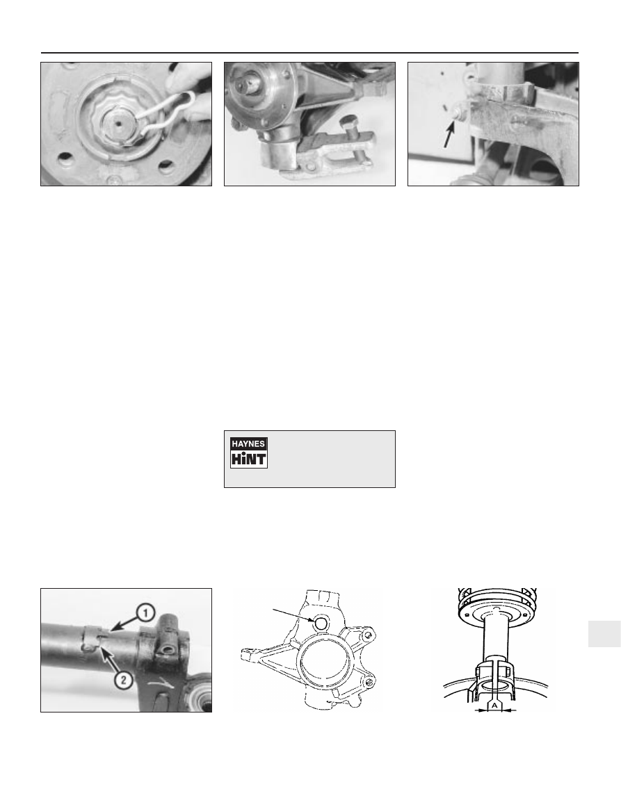
11 Similarly, slacken the lower balljoint nut
(securing the hub carrier to the lower arm),
then release the balljoint using a separator
tool (see illustration). Remove the nut.
12 Undo the nut and withdraw the hub
carrier-to-suspension strut clamp bolt, noting
that the bolt fits from the rear of the vehicle
(see illustration).
13 Where applicable, tighten the compressor
tools, and compress the spring sufficiently to
enable the lower end of the strut to be
disconnected from the hub carrier.
14 Insert a lever into the slot in the hub
carrier, and spread the slot until the hub
carrier can be released from the strut.
15 Free the hub carrier assembly from the
end of the strut, then release it from the outer
constant velocity joint splines, and remove it
from the vehicle. If necessary, tap the end of
the driveshaft (using a soft-faced mallet) to
free it from the hub carrier. Support the free,
outboard end of the driveshaft by suspending
it using wire or string - do not allow the
driveshaft to hang down under its own weight.
Refitting
16 Where applicable, fit the spring
compressor tools in position as during
removal, ensure that the driveshaft outer
constant velocity joint and hub splines are
clean, then slide the hub fully onto the
driveshaft splines.
17 Slide the hub carrier assembly fully onto
the suspension strut, aligning the slot in the
hub carrier with the lug on the base of the
strut. Also ensure that the stop boss on the
strut is in contact with the top surface of the
hub carrier (see illustration). Release the tool
used to spread the hub carrier slot.
18 Insert the hub carrier-to-suspension strut
clamp bolt from the rear side of the strut, then
fit a new nut to the clamp bolt, and tighten it
to the specified torque.
19 Two types of hub carrier may be fitted.
The later type can be identified from the hole
at the top of the assembly (see illustration).
When refitting a later type hub carrier,
proceed as follows.
a) After tightening the clamp bolt, measure
the gap between the hub carrier clamp
lugs (see illustration). The gap must not
be less than specified. If the gap is less
than specified, proceed as follows.
b) Check the condition of the lower end of
the strut. If the strut cylinder has been
crushed, the shock absorber will be
damaged, and the strut must be renewed.
c) If the strut is not damaged, but the gap
between the clamp lugs is still less than
specified, renew the hub carrier.
Suspension and steering 10•3
2.12 Hub carrier-to-suspension strut
clamp nut (arrowed)
2.19b Gap (A) on later type hub carrier
clamp lugs must not be less than 6.5 mm
2.19a Later type hub carrier with
identification hole (arrowed)
2.17 Lug (1) and stop boss (2)
on lower end of strut
2.11 Release the lower balljoint using a
balljoint separator tool
2.3 Withdraw the R-clip from the
driveshaft nut locking cap
10
To spread the slot in the hub
carrier, engage an 8.0 mm
Allen key or hexagon bit in
the slot, then turn the key/bit
to spread the slot.