Opel Movano (2018 year). Manual - part 12
Vehicle care
183
Replacing the vehicle battery
Ensure that the battery is always
replaced by the same type of battery.
Seek the assistance of a workshop to
have the vehicle battery replaced.
Stop-start system 3 137.
Charging the vehicle battery
9 Warning
On vehicles with stop-start
system, ensure that the charging
potential does not exceed
14.6 volts when using a battery
charger. Otherwise the vehicle
battery might be damaged.
9 Danger
Ensure adequate ventilation when
charging the battery. There is a
risk of explosion if gases
generated during charging are
allowed to accumulate!
Jump starting 3 213.
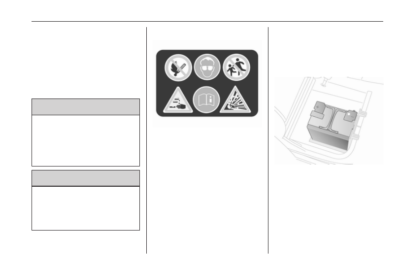
Warning label
Meaning of symbols:
● No sparks, naked flames or
smoking.
● Always shield eyes. Explosive
gases can cause blindness or
injury.
● Keep the vehicle battery out of
reach of children.
● The vehicle battery contains
sulfuric acid which could cause
blindness or serious burn
injuries.
● See the Owner's Manual for
further information.
● Explosive gas may be present in
the vicinity of the battery.
Additional battery
Depending on the vehicle's auxiliary
equipment, certain models may have
an additional battery mounted under
the right-hand front seat.
Note
The additional battery is
automatically connected to the main
vehicle battery only when the engine
is running. It does not need to be