Nissan Pathfinder (2018 year). Instruction - part 9


  Index      Nissan     Nissan Pathfinder - instruction 2018 year in english


Search            


Content   ..  7  8  9  10   ..


Nissan Pathfinder (2018 year). Instruction - part 9


SWITCH OPERATION

WARNING

In freezing temperatures the washer
solution may freeze on the windshield
and obscure your vision which may lead
to an accident. Warm the windshield
with the defroster before you wash the
windshield.

CAUTION

∙ Do not operate the washer continu-

ously for more than 30 seconds.

∙ Do not operate the washer if the

windshield-washer fluid reservoir is
empty.

∙ Do not fill the windshield-washer fluid

reservoir

with

windshield-washer

fluid concentrates at full strength.
Some

methyl

alcohol

based

windshield-washer

fluid

concen-

trates may permanently stain the
grille

if

spilled

while

filling

the

windshield-washer fluid reservoir.

∙ Pre-mix windshield-washer fluid con-

centrates with water to the manufac-
turer’s recommended levels before
pouring the fluid into the windshield-
washer fluid reservoir. Do not use the
windshield-washer fluid reservoir to
mix the windshield-washer fluid con-
centrate and water.

NOTE:

If the windshield wiper operation is in-
terrupted by snow or ice, the wiper may
stop moving to protect its motor. If this
occurs, turn the wiper switch to the OFF
position and remove the snow or ice that
is on and around the wiper arms. In ap-
proximately 1 minute, turn the switch on
again to operate the wiper.

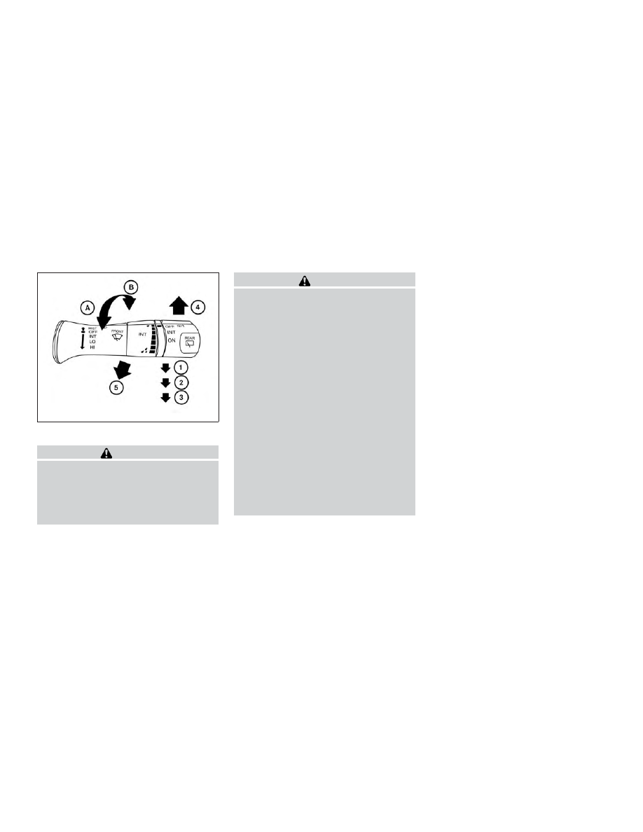
The windshield wiper and washer operates
when the ignition switch is in the ON posi-
tion.

Push the lever down to operate the wiper
at the following speed:

1

Intermittent (INT) — intermittent op-
eration can be adjusted by turning the
knob toward

A

(Slower) or

B

(Faster).

Also, the intermittent operation speed
varies in accordance with the vehicle
speed (if so equipped). (For example,
when the vehicle speed is high, the in-
termittent operation speed will be
faster.)

2

Low (LO) — continuous low speed op-
eration

3

High (HI) — continuous high speed op-
eration

LIC3028

WIPER AND WASHER SWITCH

Instruments and controls

2-37

Push the lever up

4

to have one sweep

operation (MIST) of the wiper.

Pull the lever toward you

5

to operate the

washer. The wiper will also operate several
times.

NOTE:

The Wiper with Speed feature may be
disabled. For additional information, re-
fer to “Vehicle information display” in
this section.

REAR SWITCH OPERATION

WARNING

In freezing temperatures the washer
solution may freeze on the rear window
and obscure your vision which may lead
to an accident. Warm the rear window
with the defroster before you wash the
rear window.

CAUTION

∙ Do not operate the washer continu-

ously for more than 30 seconds.

∙ Do not operate the washer if the

windshield-washer fluid reservoir is
empty.

∙ Do not fill the windshield-washer fluid

reservoir

with

windshield-washer

fluid concentrates at full strength.
Some

methyl

alcohol

based

windshield-washer

fluid

concen-

trates may permanently stain the
grille

if

spilled

while

filling

the

windshield-washer fluid reservoir.

∙ Pre-mix windshield-washer fluid con-

centrates with water to the manufac-
turer’s recommended levels before
pouring the fluid into the windshield-
washer fluid reservoir. Do not use the
windshield-washer fluid reservoir to
mix the windshield-washer fluid con-
centrate and water.

If the rear window wiper operation is inter-
rupted by snow, etc., the wiper may stop
moving to protect its motor. If this occurs,
turn the wiper switch to OFF and remove
the snow, etc. on and around the wiper

LIC3101

2-38

Instruments and controls

arms. After about 1 minute, turn the switch
on again to operate the wiper.

The rear window wiper and washer oper-
ate when the ignition switch is in the ON
position. Turn the switch clockwise from
the OFF position to operate the wiper.

1

Intermittent (INT) — intermittent op-
eration (not adjustable)

2

Low (ON) — continuous low speed op-
eration

Push the switch forward

3

to operate the

washer. The wiper will also operate several
times.

To defrost the rear window glass and out-
side mirrors (if so equipped), start the en-
gine and push the rear window defroster
switch on. The rear window defroster indi-
cator light on the switch comes on. Push
the switch again to turn the defroster off.

The rear window defroster automatically
turns off after approximately 15 minutes.

CAUTION

When cleaning the inner side of the rear
window, be careful not to scratch or
damage the rear window defroster.

NOTE:

The top and bottom few rows of wires on
the rear window are not part of the rear
window defroster system. These wires
make up the antenna for the audio sys-
tem.

LIC1388

REAR WINDOW AND OUTSIDE
MIRROR (if so equipped)
DEFROSTER SWITCH

Instruments and controls

2-39

HEADLIGHT CONTROL SWITCH

Lighting

1

Rotate the switch to the

position,

and the front parking, tail, license plate,
and instrument panel lights will come
on.

2

Rotate the switch to the

position,

and the headlights will come on and all
the other lights remain on.

CAUTION

Use the headlights with the engine run-
ning to avoid discharging the vehicle
battery.

Autolight system (if so equipped)

The autolight system allows the headlights
to turn on and off automatically. The auto-
light system can:

∙ Turn on the headlights, front parking,

tail, license plate and instrument panel
lights automatically when it is dark.

∙ Turn off all the lights when it is light.

∙ Keep all the lights on for a period of time

after you place the ignition switch in the
OFF position and all doors are closed.

Type A (if so equipped)

LIC3240

Type B (if so equipped)

LIC3237

LIC3188

HEADLIGHT AND TURN SIGNAL
SWITCH

2-40

Instruments and controls

∙ Turn on the headlights if the windshield

wipers

make

multiple

continuous

passes within approximately one min-
ute of the first pass (if so equipped). The
headlights remain on until the wipers
are turned off for a short period of time.

NOTE:

Autolight activation sensitivity and the
time delay for autolight shutoff can be
adjusted. For additional information, re-
fer to “Vehicle information display” in
this section.

To turn on the autolight system:

∙ Place the headlight switch in the AUTO

position

1

.

∙ Place the ignition switch in the ON posi-

tion.

∙ The autolight system automatically

turns the headlights on and off.

Initially, if the ignition switch is turned OFF
and a door is opened and left open, the
headlights remain ON for a period of time. If
another door is opened while the head-
lights are on, then the timer is reset.

To turn the autolight system off, place the

switch in the OFF,

, or

position.

Be sure you do not put anything on top
of the autolight sensor located in the top
side of the instrument panel

1

. The au-

tolight sensor controls the autolight; if it
is covered, the autolight sensor reacts as
if it is dark out and the headlights will
illuminate. If this occurs while parked
with the engine off and the ignition
switch placed in the ON position, your
vehicle’s battery could become dis-
charged.

Headlight beam select

1

To select the high beam function, push
the lever forward while the low beams
are on. The high beam lights come on
and the

indicator light illuminates.

2

Pull the lever back to return to the low
beam.

3

Pulling and releasing the lever flashes
the headlight high beams on and off.
The low beams do not need to be on
for this to function.

LIC2237

LIC3250

Instruments and controls

2-41

Battery saver system

If the ignition switch is placed in the OFF
position while the headlight switch is in

the

or

position, the headlights

will turn off after a period of time.

NOTE:

The Battery Saver system may be dis-
abled. For additional information, refer
to “Vehicle information display” in this
section.

CAUTION

Even though the battery saver feature
automatically turns off the headlights
after a period of time, you should turn
the headlight switch to the OFF position
when the engine is not running to avoid
discharging the vehicle battery.

LED DAYTIME RUNNING LIGHTS
(DRL) SYSTEM

The LED portion of the headlights auto-
matically illuminate at 100% intensity when
the engine is started and the parking brake
is released. The LED Daytime Running
Lights (DRL) operate with the headlight
switch in the OFF position. When you turn
the headlight switch to the

position

for full illumination, the LED lights switch
from LED DRL to the park function.
If the parking brake is applied before the
engine is started, the LED DRL do not illumi-
nate. The LED DRL illuminate when the
parking brake is released. The LED DRL re-
main on until the ignition is placed in the
OFF position.

It is necessary at dusk to turn the headlight
switch on for interior controls and switches
to illuminate, as those remain off while the
switch is in the OFF position.

WARNING

When the LED DRL system is active, tail
lights on your vehicle are not on. It is
necessary at dusk to turn on your head-
lights. Failure to do so could cause an
accident injuring yourself and others.

INSTRUMENT BRIGHTNESS
CONTROL

Press the “+” button

A

to increase the

brightness of instrument panel lights.

Press the “-” button

B

to decrease the

brightness of instrument panel lights.

LIC2389

2-42

Instruments and controls

TURN SIGNAL SWITCH

Turn signal

1

Move the lever up or down to signal the
turning direction. When the turn is
completed, the turn signal cancels au-
tomatically.

Lane change signal

2

Move the lever up or down until the
turn signal begins to flash, but the lever
does not latch, to signal a lane change.
Hold the lever until the lane change is
completed.

Move the lever up or down until the
turn signal begins to flash, but the lever
does not latch, and release the lever.
The turn signal will automatically flash
three times.

Choose the appropriate method to signal
a lane change based on road and traffic
conditions.

FOG LIGHT SWITCH (if so
equipped)

To turn the fog lights on, rotate the head-
light switch to the

position, then ro-

tate the fog light switch to the

posi-

tion.
To turn the fog lights on with the headlight
switch in the AUTO position, the headlights
must be on, then rotate the fog light switch
to the

position.

To turn the fog lights off, rotate the fog light
switch to the OFF position.

LIC3252

LIC3256

Instruments and controls

2-43

The headlights must be on and the low
beams selected for the fog lights to oper-
ate. The fog lights automatically turn off
when the high beam headlights are se-
lected.

To sound the horn, push the center pad
area of the steering wheel.

WARNING

Do not use or allow occupants to use
the climate controlled seats if you or the
occupants can not monitor seat tem-
peratures or have an inability to feel
pain in those body parts in contact with
the seat. Use of the climate controlled
seats by such people could result in se-
rious injury.

LIC2227

LIC3768

HORN

CLIMATE CONTROLLED SEAT
SWITCHES (if so equipped)

2-44

Instruments and controls

CAUTION

∙ The battery could run down if the cli-

mate control seat is operated while
the engine is not running.

∙ Do not use the climate control seat for

extended periods or when no one is
using the seat.

∙ Do not put anything on the seat which

insulates heat, such as a blanket,
cushion, seat cover, etc. Otherwise,
the seat may become overheated.

∙ Do not place anything hard or heavy

on the seat or pierce it with a pin or
similar objects. This may result in
damage to the climate controlled
seat.

∙ Any liquid spilled on the seat should

be removed immediately with a dry
cloth

∙ The climate controlled seat has an air

filter. Do not operate the climate con-
trolled seat without an air filter. This
may result in damage to the system.

∙ When cleaning the seat, never use

gasoline, benzine, thinner, or any
similar materials.

∙ If any malfunctions are found or the

climate controlled seat does not oper-
ate, turn the switch off and have the
system checked. It is recommended
that you visit a NISSAN dealer for this
service.

The climate controlled seat warms up or
cools down the front seat by blowing warm
or cool air from under the surface of the
seat. The climate control switch is located
on the center console.

The climate controlled seat can be oper-
ated as follows:

1. Start the engine.

2. Turn the control knob

A

to the heat

side

1

or the cool side

2

. The indica-

tor light

B

on the control knob will illu-

minate.

3. Adjust the desired amount of air using

the control knob. The climate con-
trolled seat blower remains on low
speed for approximately 60 seconds
after turning the switch on or selecting
the desired temperature.

4. When the vehicle’s interior is warmed

or cooled, or before you leave the ve-
hicle, be sure to turn the control knob
to the OFF (center) position. The indica-
tor light

B

on the control knob goes off

with the switch in the OFF (center) po-
sition.

To check the air filter for the climate con-
trolled seat, it is recommended that you
visit a NISSAN dealer.

Instruments and controls

2-45

WARNING

Do not use or allow occupants to use
the seat heater if you or the occupants
cannot monitor elevated seat tempera-
tures or have an inability to feel pain in
body parts that contact the seat. Use of
the seat heater by such people could
result in serious injury.

CAUTION

∙ The battery could run down if the seat

heater is operated while the engine is
not running.

∙ Do not use the seat heater for ex-

tended periods or when no one is us-
ing the seat.

∙ Do not put anything on the seat which

insulates heat, such as a blanket,
cushion, seat cover, etc. Otherwise,
the seat may become overheated.

∙ Do not place anything hard or heavy

on the seat or pierce it with a pin or
similar object. This may result in dam-
age to the heater.

∙ Any liquid spilled on the heated seat

should be removed immediately with
a dry cloth.

∙ When cleaning the seat, never use

gasoline, benzine, thinner, or any
similar materials.

∙ If any malfunctions are found or the

heated seat does not operate, turn
the switch off and have the system
checked. It is recommended that you
visit a NISSAN dealer for this service.

The front seats are warmed by built-in
heaters.

1. Start the engine.

2. Push the LO or HI position of the switch,

as desired. The indicator light in the
switch will illuminate.

The heater is controlled by a thermo-
stat, automatically turning the heater
on and off. The indicator light will re-
main on as long as the switch is on.

3. When the seat is warmed or before you

leave the vehicle, be sure to push the
switch to turn it off.

LIC3037

HEATED SEAT SWITCHES (if so
equipped)

2-46

Instruments and controls

WARNING

Do not use or allow occupants to use
the seat heater if you or the occupants
cannot monitor elevated seat tempera-
tures or have an inability to feel pain in
body parts that contact the seat. Use of
the seat heater by such people could
result in serious injury.

CAUTION

∙ The battery could run down if the seat

heater is operated while the engine is
not running.

∙ Do not use the seat heater for ex-

tended periods or when no one is us-
ing the seat.

∙ Do not put anything on the seat which

insulates heat, such as a blanket,
cushion, seat cover, etc. Otherwise,
the seat may become overheated.

∙ Do not place anything hard or heavy

on the seat or pierce it with a pin or
similar object. This may result in dam-
age to the heater.

∙ Any liquid spilled on the heated seat

should be removed immediately with
a dry cloth.

∙ When cleaning the seat, never use

gasoline, benzine, thinner, or any
similar materials.

∙ If any malfunctions are found or the

heated seat does not operate, turn
the switch off and have the system
checked. It is recommended that you
visit a NISSAN dealer for this service.

The 2nd row seats are warmed by built-in
heaters. The switches are located on the
rear of the front center console and can be
operated independently of each other.

1. Start the engine.

2. Push the LO or HI position of the switch,

as desired. The indicator light in the
switch will illuminate.

The heater is controlled by a thermo-
stat, automatically turning the heater
on and off. The indicator light will re-
main on as long as the switch is on.

LIC3037

HEATED 2ND ROW SEAT SWITCHES (if
so equipped)

Instruments and controls

2-47

3. When the seat is warmed or before you

leave the vehicle, be sure to turn the
switch off.

The heated steering wheel system is de-
signed to operate only when the surface
temperature of the steering wheel is below
68°F (20°C).

Push the heated steering wheel switch to
warm the steering wheel after the engine
starts. The indicator light will come on.

If the surface temperature of the steering
wheel is below 68°F (20°C), the system will
heat the steering wheel and cycle off and
on to maintain a temperature above 68°F
(20°C). The indicator light will remain on as
long as the system is on.

Push the switch again to turn the heated
steering wheel system off manually. The
indicator light will go off.

NOTE:

If the surface temperature of the steer-
ing wheel is above 68°F (20°C) when the
switch is turned on, the system will not
heat the steering wheel. This is not a
malfunction.

LIC2221

HEATED STEERING WHEEL SWITCH (if
so equipped)

2-48

Instruments and controls

The vehicle should be driven with the VDC
system on for most driving conditions.

If the vehicle is stuck in mud or snow, the
VDC system reduces the engine output to
reduce wheel spin. The engine speed will
be reduced even if the accelerator is de-
pressed to the floor. If maximum engine
power is needed to free a stuck vehicle,
turn the VDC system off.

To turn off the VDC system, push the VDC
OFF switch. The

indicator will come

on.

Push the VDC OFF switch again or restart
the engine to turn on the system. For addi-
tional information, refer to “Vehicle Dy-
namic Control (VDC) system” in the “Start-
ing and driving” section of this manual.

WARNING

∙ Never rely solely on the hill descent

control system to control vehicle
speed when driving on steep downhill
grades. Always drive carefully when
using the hill descent control system
and decelerate the vehicle speed by
depressing the brake pedal if neces-
sary. Be especially careful when driv-
ing on frozen, muddy or extremely
steep downhill roads. Failure to con-
trol vehicle speed may result in a loss
of control of the vehicle and possible
serious injury or death.

LIC3344

LIC3435

VEHICLE DYNAMIC CONTROL (VDC)
OFF SWITCH

HILL DESCENT CONTROL SWITCH (if
so equipped)

Instruments and controls

2-49

∙ The hill descent control may not con-

trol the vehicle speed on a hill under
all load or road conditions. Always be
prepared to depress the brake pedal
to control vehicle speed. Failure to do
so may result in a collision or serious
personal injury.

CAUTION

When the hill descent control system
operates continuously for a long time,
the temperature of the brake pads may
increase and the hill descent control
system may be temporarily disabled
(the indicator light will blink). If the indi-
cator light does not come on continu-
ously after blinking, stop using the
system.

The hill descent control system is designed
to reduce driver workload when going
down steep hills. The hill descent control
system helps to control vehicle speed so
the driver can concentrate on steering the
vehicle.

To activate the hill descent control system:

∙ the 4WD switch must be in the LOCK

position and the vehicle speed must be
under 15 mph (25 km/h)

∙ the hill descent control system switch

must be ON.

The hill descent control system ON indica-
tor light will come on when the system is
activated. Also, the stop/tail lights illumi-
nate while the hill descent control system
applies the brakes to control vehicle speed.

If the accelerator or brake pedal is de-
pressed while the hill descent control sys-
tem is on, the system will stop operating
temporarily. As soon as the accelerator or
brake pedal is released, the hill descent
control system begins to function again if
the hill descent control operating condi-
tions are fulfilled.

The hill descent control system ON indica-
tor light blinks if the switch is on and all
conditions for system activation are not
met or if the system becomes disengaged
for any reason.

To turn off the hill descent control system,
push the switch to the OFF position.

For additional information, refer to “Hill de-
scent control system ON indicator light” in
this section and “Hill descent control sys-
tem” in the “Starting and driving” section of
this manual.

The rear door alert system functions under
certain conditions to indicate there may be
an object or passenger in the rear seat(s).
Check the seat(s) before exiting the vehicle.

The rear door alert system is initially dis-
abled. The driver can enable the system
using the vehicle information display. For
additional information, refer to “Vehicle in-
formation display warnings and indicators”
in this section.

When the system is enabled:

∙ The system is activated when a rear

door is opened and closed approxi-
mately 10 minutes before the vehicle is
started. When the vehicle is started and
the system is activated, a visual mes-
sage appears in the vehicle information
display. For additional information, refer
to “Rear Door Alert is activated” in this
section.

∙ If a rear door is opened and closed but

the vehicle is not started within approxi-
mately 10 minutes, the system will not
be activated. A rear door must be
opened and closed and the car started
within 10 minutes for the system to ac-
tivate.

REAR DOOR ALERT

2-50

Instruments and controls

When the rear door alert system is acti-
vated and a driver exits the vehicle after
arriving at a destination:

∙ When the driver puts the vehicle in the P

(Park) position, a message appears in
the vehicle information display for a
driver to “Dismiss Message” or “Disable
Alert” if desired.

∙ With the system enabled, when the

driver exits the vehicle, an audible alert
(horn sound) will occur unless a rear
door is opened and closed within a
short time to deactivate the alert.

∙ If the doors are locked before the alert is

deactivated by opening a rear door, the
horn will sound.

∙ If the system is activated but the rear

liftgate is opened before opening a rear
door, the horn will be delayed until after
the liftgate is closed.

∙ If the audible horn alert occurs, a mes-

sage will also appear in the vehicle in-
formation display that states, “Check
Back Seat for All Articles”.

WARNING

• If the driver selects “Disable Alert”, no
audible alert will be provided regard-
less of rear door open/close status.

• There may be times when there is an
object or passenger in the rear seat(s)
but the audible alert does not sound.
For example, this may occur if the en-
gine is turned off and then on again in a
short period of time during a trip, or if
rear seat passengers enter or exit the
vehicle during a trip.

• The system does not directly detect
objects or passengers in the rear
seat(s). Instead, it can detect when a
rear door is opened and closed, indicat-
ing that there may be something in the
rear seat(s).

NOTE:

There may be times when the horn
sounds but there are no objects or pas-
sengers in the rear seat(s).

For additional information, refer to “Rear
Door Alert is activated” in this section.

The warning systems switch is used to turn
on and off the Blind Spot Warning (BSW)
system that is activated using the settings
menu on the vehicle information display.

When the warning systems switch is
turned off, the indicator

1

on the switch is

off. The indicator will also be off if the warn-
ing system is deactivated using the set-
tings menu.

The BSW system will turn on the side indi-
cator light, located next to the outside mir-
rors, if the radar detects a vehicle in the
detection zone. If the turn signal is acti-
vated in the direction of the detected ve-
hicle, a chime sounds twice and the side

LSD2208

WARNING SYSTEMS SWITCH (if so
equipped)

Instruments and controls

2-51

indicator light will flash. For additional infor-
mation, refer to “Blind Spot Warning (BSW)”
in the “Starting and driving” section of this
manual.

To use the outlets for devices that require
120v power, place the ignition in the ON
position and push the power inverter
switch.

The switch will illuminate when enabled.

CAUTION

∙ Use power outlets with the engine

running to avoid discharging the ve-
hicle battery.

∙ Do not attempt to use this while

driving.

∙ Do not use double adapters or more

than one electrical accessory, doing
so could significantly drain the bat-
tery of your vehicle.

LIC2231

POWER INVERTER SWITCH (if so
equipped)

2-52

Instruments and controls


Content   ..  7  8  9  10   ..