Nissan Altima L32. Manual - part 629
EM-52
< ON-VEHICLE REPAIR >
[QR25DE]
TIMING CHAIN
TIMING CHAIN
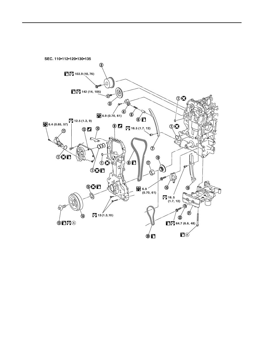
Removal and Installation
INFOID:0000000004202125
CAUTION:
Apply new engine oil to parts as indicated in the illustration before installation.
REMOVAL
1. Support the engine and transaxle assembly with suitable tools.
1.
O-rings
2.
Camshaft sprocket (INT)
3.
Camshaft sprocket (EXH)
4.
Chain tensioner
5.
Spring
6.
Chain tensioner plunger
7.
Timing chain slack guide
8.
Timing chain
9.
Front cover
10. Chain guide
11. IVT solenoid valve
12. IVT cover
13. Crankshaft pulley bolt
14. Crankshaft pulley
15. Front oil seal
16. Balancer unit timing chain tensioner
17. Oil pump drive spacer
18. Crankshaft sprocket
19. Timing chain tension guide
20. Balancer unit timing chain
21. Balancer unit
22. Balancer unit sprocket
A.
Follow the installation procedure
AWBIA0592GB