Nissan Altima L32. Manual - part 406


  Index      Nissan     Nissan Altima L32 (2007-2009 year) - Service and Repair Manual


Search            


Content   ..  404  405  406  407   ..


Nissan Altima L32. Manual - part 406


P0138 HO2S2

EC-745

< COMPONENT DIAGNOSIS >

[QR25DE EXCEPT FOR CALIFORNIA]

C

D

E

F

G

H

I

J

K

L

M

A

EC

N

P

O

P0138 HO2S2

Description

INFOID:0000000004349716

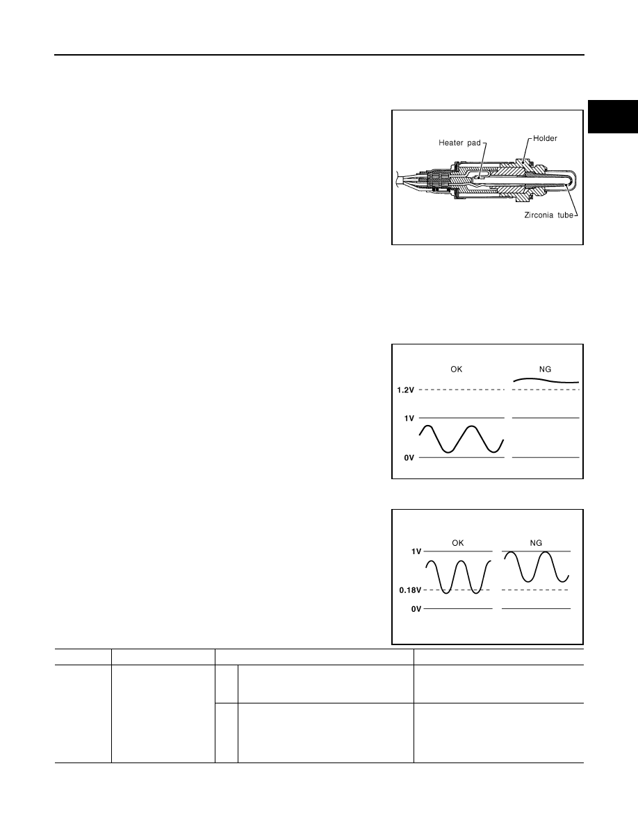
The heated oxygen sensor 2, after three way catalyst (manifold),

monitors the oxygen level in the exhaust gas on each bank.

Even if switching characteristics of the air fuel ratio (A/F) sensor 1

are shifted, the air-fuel ratio is controlled to stoichiometric, by the sig-

nal from the heated oxygen sensor 2.

This sensor is made of ceramic zirconia. The zirconia generates volt-

age from approximately 1V in richer conditions to 0V in leaner condi-

tions.

Under normal conditions the heated oxygen sensor 2 is not used for

engine control operation.

DTC Logic

INFOID:0000000004349717

DTC DETECTION LOGIC

The heated oxygen sensor 2 has a much longer switching time between rich and lean than the air fuel ratio (A/

F) sensor 1. The oxygen storage capacity of the three way catalyst (manifold) causes the longer switching

time.

MALFUNCTION A

To judge the malfunctions of heated oxygen sensor 2, ECM monitors

whether the voltage is unusually high during the various driving con-

dition such as fuel-cut.

MALFUNCTION B

To judge the malfunctions of heated oxygen sensor 2, ECM monitors

whether the minimum voltage of sensor is sufficiently low during the

various driving condition such as fuel-cut.

DTC CONFIRMATION PROCEDURE

SEF327R

PBIB1848E

PBIB2376E

DTC No.

Trouble diagnosis name

DTC detecting condition

Possible cause

P0138

Heated oxygen sensor 2 
circuit high voltage

A)

An excessively high voltage from the sen-
sor is sent to ECM.

• Harness or connectors

(The sensor circuit is open or shorted)

• Heated oxygen sensor 2

B)

The minimum voltage from the sensor is 
not reached to the specified voltage.

• Harness or connectors

(The sensor circuit is open or shorted)

• Heated oxygen sensor 2
• Fuel pressure
• Fuel injector

EC-746

< COMPONENT DIAGNOSIS >

[QR25DE EXCEPT FOR CALIFORNIA]

P0138 HO2S2

1.

PRECONDITIONING

If DTC Confirmation Procedure has been previously conducted, always turn ignition switch OFF and wait at

least 10 seconds before conducting the next test.

>> GO TO 2.

2.

PERFORM DTC CONFIRMATION PROCEDURE FOR MALFUNCTION A

1. Start engine and warm it up to the normal operating temperature.

2. Turn ignition switch OFF and wait at least 10 seconds.

3. Start engine and keep the engine speed between 3,500 and 4,000 rpm for at least 1 minute under no load.

4. Check 1st trip DTC.
Is 1st trip DTC detected?

YES

>> Go to 

EC-747, "Diagnosis Procedure"

.

NO-1 >> With CONSULT-III: GO TO 3.

NO-2 >> Without CONSULT-III: GO TO 5.

3.

PERFORM DTC CONFIRMATION PROCEDURE FOR MALFUNCTION B

NOTE:

For better results, perform “DTC WORK SUPPORT” at a temperature of 0 to 30 

°C (32 to 86 °F).

1. Turn ignition switch ON and select “DATA MONITOR” mode with CONSULT-III.

2. Start engine and warm it up to the normal operating temperature.

3. Turn ignition switch OFF and wait at least 10 seconds.

4. Start engine and keep the engine speed between 3,500 and 4,000 rpm for at least 1 minute under no load.

5. Let engine idle for 1 minute.

6. Make sure that “COOLAN TEMP/S” indicates more than 70

°C (158°F).

If not, warm up engine and go to next step when “COOLAN TEMP/S” indication reaches to 70

°C (158°F).

7. Open engine hood.

8. Select “HO2S2 (B1) P1146” of “HO2S2” in “DTC WORK SUPPORT” mode with CONSULT-III.

9. Follow the instruction of CONSULT-III.

NOTE:

It will take at most 10 minutes until “COMPLETED” is displayed.

10. Touch “SELF-DIAG RESULT”.
Which is displayed on CONSULT-III

OK

>> INSPECTION END

NG

>> Go to 

EC-747, "Diagnosis Procedure"

.

CAN NOT BE DIAGNOSED>>GO TO 4.

4.

PERFORM DTC CONFIRMATION PROCEDURE FOR MALUNCTION B AGAIN

1. Turn ignition switch OFF and leave the vehicle in a cool place (soak the vehicle).

2. Perform DTC CONFIRMATION PROCEDURE again.

>> GO TO 3.

5.

PERFORM COMPONENT FUNCTION CHECK FOR MALFUNCTION B

Perform component function check. Refer to 

EC-747, "Diagnosis Procedure"

.

NOTE:

Use component function check to check the overall function of the heated oxygen sensor 2 circuit. During this

check, a 1st trip DTC might not be confirmed.
Is the inspection result normal?

YES

>> INSPECTION END

NO

>> Go to 

EC-747, "Diagnosis Procedure"

.

Component Function Check

INFOID:0000000004349718

1.

PERFORM COMPONENT FUNCTION CHECK-I

Without CONSULT-III

1. Start engine and warm it up to the normal operating temperature.

P0138 HO2S2

EC-747

< COMPONENT DIAGNOSIS >

[QR25DE EXCEPT FOR CALIFORNIA]

C

D

E

F

G

H

I

J

K

L

M

A

EC

N

P

O

2. Turn ignition switch OFF and wait at least 10 seconds.

3. Start engine and keep the engine speed between 3,500 and 4,000 rpm for at least 1 minute under no load.

4. Let engine idle for 1 minute.

5. Check the voltage between ECM harness connector and ground

under the following condition.

Is the inspection result normal?

YES

>> INSPECTION END

NO

>> GO TO 2.

2.

PERFORM COMPONENT FUNCTION CHECK-II

Check the voltage between ECM harness connector and ground

under the following condition.

Is the inspection result normal?

YES

>> INSPECTION END

NO

>> GO TO 3.

3.

PERFORM COMPONENT FUNCTION CHECK-III

Check the voltage between ECM harness connector and ground

under the following condition.

Is the inspection result normal?

YES

>> INSPECTION END

NO

>> Go to 

EC-747, "Diagnosis Procedure"

.

Diagnosis Procedure

INFOID:0000000004349719

1.

INSPECTION START

Confirm the detected malfunction (A or B). Refer to 

EC-745, "DTC Logic"

.

Which malfunction is detected?

A

>> GO TO 2.

B

>> GO TO 9.

2.

CHECK GROUND CONNECTION

ECM

Ground

Condition

Voltage

Con-

nector

Termi-

nal

F13

33

(HO2S

2 sig-

nal)

Ground

Revving up to 4,000 
rpm under no load 
at least 10 times

The voltage should be above 
0.18V at least once during this 
procedure.

JMBIA1586ZZ

ECM

Ground

Condition

Voltage

Con-

nector

Termi-

nal

F13

33

(HO2S

2 sig-

nal)

Ground

Keeping engine speed 
at idle for 10 minutes

The voltage should be above 
0.18V at least once during 
this procedure.

JMBIA1587ZZ

ECM

Ground

Condition

Voltage

Con-

nector

Termi-

nal

F13

33

(HO2S

2 sig-

nal)

Ground

Coasting from 80 km/h (50 
MPH) in D position (CVT), 
4th gear position (M/T)

The voltage should be 
above 0.18V at least 
once during this proce-
dure.

JMBIA1588ZZ

EC-748

< COMPONENT DIAGNOSIS >

[QR25DE EXCEPT FOR CALIFORNIA]

P0138 HO2S2

1. Turn ignition switch OFF.

2. Check ground connection E9. Refer to Ground Inspection in 

GI-45, "Circuit Inspection"

.

Is the inspection result normal?

YES

>> GO TO 3.

NO

>> Repair or replace ground connection.

3.

CHECK HO2S2 GROUND CIRCUIT FOR OPEN AND SHORT

1. Disconnect heated oxygen sensor 2 harness connector.

2. Disconnect ECM harness connector.

3. Check the continuity between HO2S2 harness connector and ECM harness connector.

4. Also check harness for short to ground and short to power.
Is the inspection result normal?

YES

>> GO TO 4.

NO

>> Repair open circuit or short to ground or short to power in harness or connectors.

4.

CHECK HO2S2 INPUT SIGNAL CIRCUIT FOR OPEN AND SHORT

1. Check the continuity between HO2S2 harness connector and ECM harness connector.

2. Check the continuity between HO2S2 harness connector or ECM harness connector and ground.

3. Also check harness for short to power.
Is the inspection result normal?

YES

>> GO TO 5.

NO

>> Repair open circuit or short to ground or short to power in harness or connectors.

5.

CHECK HO2S2 CONNECTOR FOR WATER

Check connectors for water.

Is the inspection result normal?

YES

>> GO TO 6.

NO

>> Repair or replace harness or connectors.

6.

CHECK HEATED OXYGEN SENSOR 2

Refer to 

EC-750, "Component Inspection"

.

Is the inspection result normal?

YES

>> GO TO 8.

NO

>> GO TO 7.

7.

REPLACE HEATED OXYGEN SENSOR 2

Replace heated oxygen sensor 2.

CAUTION:

HO2S2

ECM

Continuity

Connector Terminal Connector Terminal

F42

1

F13

35

Existed

HO2S2

ECM

Continuity

Connector Terminal Connector Terminal

F42

4

F13

33

Existed

HO2S2

ECM

Ground

Continuity

Connector Terminal Connector Terminal

F42

4

F13

33

Ground Not existed

Water should not exist.


Content   ..  404  405  406  407   ..