Nissan Altima L32. Manual - part 384
 

  Index      Nissan     Nissan Altima L32 (2007-2009 year) - Service and Repair Manual


Search            


Content   ..  382  383  384  385   ..


Nissan Altima L32. Manual - part 384


ON BOARD DIAGNOSTIC (OBD) SYSTEM

EC-657

< FUNCTION DIAGNOSIS >

[QR25DE EXCEPT FOR CALIFORNIA]

C

D

E

F

G

H

I

J

K

L

M

A

EC

N

P

O

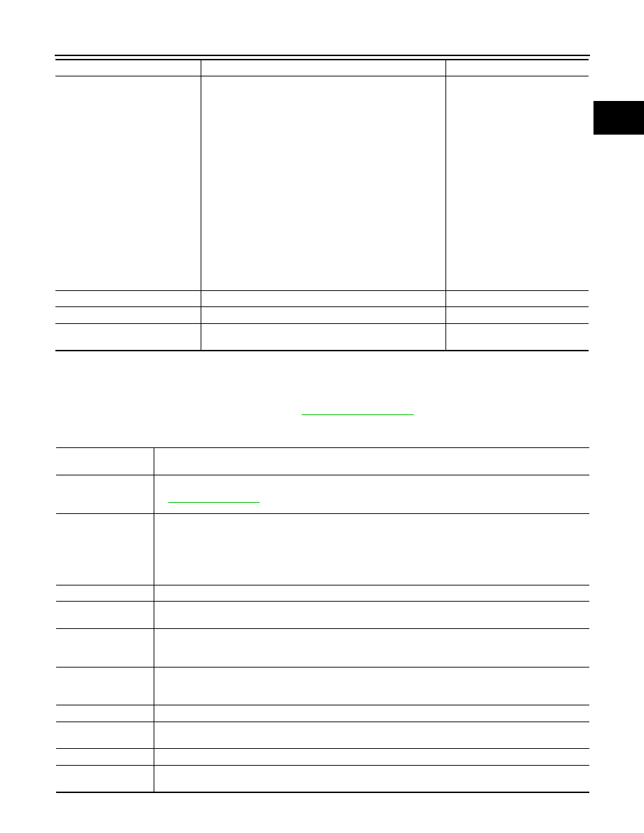
*: This function is not necessary in the usual service procedure.

SELF-DIAG RESULTS MODE

Self Diagnostic Item

Regarding items of DTC and 1st trip DTC, refer to 

EC-1015, "DTC Index"

.)

Freeze Frame Data and 1st Trip Freeze Frame Data

EVAP SYSTEM CLOSE

CLOSE THE EVAP CANISTER VENT CONTROL VALVE IN 
ORDER TO MAKE EVAP SYSTEM CLOSE UNDER THE 
FOLLOWING CONDITIONS.
• IGN  SW  ON
• ENGINE NOT RUNNING
• AMBIENT TEMPERATURE IS ABOVE 0

°C (32°F).

• NO VACUUM AND NO HIGH PRESSURE IN EVAP SYS-

TEM

•  FUEL TANK TEMP. IS MORE THAN 0

°C (32°F).

• WITHIN 10 MINUTES AFTER STARTING “EVAP SYS-

TEM CLOSE”

• WHEN TRYING TO EXECUTE “EVAP SYSTEM CLOSE” 

UNDER THE CONDITION EXCEPT ABOVE, CONSULT-
II WILL DISCONTINUE IT AND DISPLAY APPROPRIATE 
INSTRUCTION.
NOTE:
WHEN STARTING ENGINE, CONSULT-III MAY DIS-
PLAY “BATTERY VOLTAGE IS LOW. CHARGE BAT-
TERY”, EVEN IN USING CHARGED BATTERY.

When detecting EVAP vapor leak 
point of EVAP system

VIN REGISTRATION

• IN THIS MODE, VIN IS REGISTERED IN ECM.

When registering VIN in ECM

TARGET IDLE RPM ADJ*

• IDLE CONDITION

When setting target idle speed

TARGET IGN TIM ADJ*

• IDLE CONDITION

When adjusting target ignition tim-
ing

WORK ITEM

CONDITION

USAGE

Freeze frame data 

item*

Description

DIAG TROUBLE 
CODE
[PXXXX]

• The engine control component part/control system has a trouble code, it is displayed as PXXXX. (Refer to 

EC-1015, "DTC Index"

.)

FUEL SYS-B1

• “Fuel injection system status” at the moment a malfunction is detected is displayed.
• One mode in the following is displayed.

Mode2: Open loop due to detected system malfunction
Mode3: Open loop due to driving conditions (power enrichment, deceleration enleanment)
Mode4: Closed loop - using oxygen sensor(s) as feedback for fuel control
Mode5: Open loop - has not yet satisfied condition to go to closed loop

CAL/LD VALUE [%]

• The calculated load value at the moment a malfunction is detected is displayed.

COOLANT TEMP [

°C] 

or [

°F]

• The engine coolant temperature at the moment a malfunction is detected is displayed.

L-FUEL TRM-B1 [%]

• “Long-term fuel trim” at the moment a malfunction is detected is displayed.
• The long-term fuel trim indicates much more gradual feedback compensation to the base fuel schedule than 

short-term fuel trim.

S-FUEL TRM-B1 [%]

• “Short-term fuel trim” at the moment a malfunction is detected is displayed.
• The short-term fuel trim indicates dynamic or instantaneous feedback compensation to the base fuel sched-

ule.

ENGINE SPEED [rpm] • The engine speed at the moment a malfunction is detected is displayed.

VEHICL SPEED
[km/h] or [mph]

• The vehicle speed at the moment a malfunction is detected is displayed.

ABSOL TH·P/S [%]

• The throttle valve opening angle at the moment a malfunction is detected is displayed.

B/FUEL SCHDL 
[msec]

• The base fuel schedule at the moment a malfunction is detected is displayed.

EC-658

< FUNCTION DIAGNOSIS >

[QR25DE EXCEPT FOR CALIFORNIA]

ON BOARD DIAGNOSTIC (OBD) SYSTEM

*: The items are the same as those of 1st trip freeze frame data.

DATA MONITOR MODE

Monitored Item

×: Applicable

INT/A TEMP SE [

°C] 

or [

°F]

• The intake air temperature at the moment a malfunction is detected is displayed.

FUEL SYS-B2

• These items displayed but are not applicable to this model.

L-FUEL TRM-B2 [%]

S-FUEL TRM-B2 [%]

INT MANI PRES [kPa] 

COMBUST CONDI-
TION

Freeze frame data 

item*

Description

Monitored item

Unit

Description

Remarks

ENG SPEED

rpm

• Indicates the engine speed computed from the 

signal of the crankshaft position sensor (POS) 
and camshaft position sensor (PHASE).

• Accuracy becomes poor if engine 

speed drops below the idle rpm.

• If the signal is interrupted while the 

engine is running, an abnormal value 
may be indicated.

MAS A/F SE-B1

V

• The signal voltage of the mass air flow sensor is 

displayed.

• When the engine is stopped, a certain 

value is indicated.

• When engine is running specification 

range is indicated in “SPEC”.

B/FUEL SCHDL

ms

• “Base fuel schedule” indicates the fuel injection 

pulse width programmed into ECM, prior to any 
learned on board correction.

• When engine is running specification 

range is indicated in “SPEC”.

A/F ALPHA-B1

%

• The mean value of the air-fuel ratio feedback cor-

rection factor per cycle is indicated.

• When the engine is stopped, a certain 

value is indicated.

• When engine is running specification 

range is indicated in “SPEC”.

• This data also includes the data for 

the air-fuel ratio learning control.

COOLAN TEMP/S

°C or °F

• The engine coolant temperature (determined by 

the signal voltage of the engine coolant tempera-
ture sensor) is displayed.

• When the engine coolant temperature 

sensor is open or short-circuited, 
ECM enters fail-safe mode. The en-
gine coolant temperature determined 
by the ECM is displayed.

A/F SEN1 (B1)

V

• The A/F signal computed from the input signal of 

the air fuel ratio (A/F) sensor 1 is displayed.

HO2S2 (B1)

V

• The signal voltage of the heated oxygen sensor 2 

is displayed.

HO2S2 MNTR(B1)

RICH/LEAN

• Display of heated oxygen sensor 2 signal:

RICH: means the amount of oxygen after three 
way catalyst is relatively small.
LEAN: means the amount of oxygen after three 
way catalyst is relatively large.

• When the engine is stopped, a certain 

value is indicated.

VHCL SPEED SE

km/h or mph

• The vehicle speed computed from the vehicle 

speed signal sent from combination meter is dis-
played.

BATTERY VOLT

V

• The power supply voltage of ECM is displayed.

ACCEL SEN 1

V

• The accelerator pedal position sensor signal volt-

age is displayed.

• ACCEL SEN 2 signal is converted by 

ECM internally. Thus, it differs from 
ECM terminal voltage signal.

ACCEL SEN 2

ON BOARD DIAGNOSTIC (OBD) SYSTEM

EC-659

< FUNCTION DIAGNOSIS >

[QR25DE EXCEPT FOR CALIFORNIA]

C

D

E

F

G

H

I

J

K

L

M

A

EC

N

P

O

TP SEN 1-B1

V

• The throttle position sensor signal voltage is dis-

played.

• TP SEN 2-B1 signal is converted by 

ECM internally. Thus, it differs from 
ECM terminal voltage signal.

TP SEN 2-B1

FUEL T/TMP SE

°C or °F

• The fuel temperature (determined by the signal 

voltage of the fuel tank temperature sensor) is 
displayed.

INT/A TEMP SE

°C or °F

• The intake air temperature (determined by the 

signal voltage of the intake air temperature sen-
sor) is indicated.

EVAP SYS PRES

V

• The signal voltage of EVAP control system pres-

sure sensor is displayed.

FUEL LEVEL SE

V

• The signal voltage of the fuel level sensor is dis-

played.

START SIGNAL

ON/OFF

• Indicates start signal status [ON/OFF] computed 

by the ECM according to the signals of engine 
speed and battery voltage.

• After starting the engine, [OFF] is dis-

played regardless of the starter sig-
nal.

CLSD THL POS

ON/OFF

• Indicates idle position [ON/OFF] computed by 

ECM according to the accelerator pedal position 
sensor signal.

AIR COND SIG

ON/OFF

• Indicates [ON/OFF] condition of the air condition-

er switch as determined by the air conditioner sig-
nal.

P/N POSI SW

ON/OFF

• Indicates [ON/OFF] condition from the park/neu-

tral position (PNP) switch signal.

PW/ST SIGNAL

ON/OFF

• [ON/OFF] condition of the power steering system 

(determined by the signal voltage of the power 
steering pressure sensor) is indicated.

LOAD SIGNAL

ON/OFF

• Indicates [ON/OFF] condition from the electrical 

load signal.
ON: Rear window defogger switch is ON and/or 
lighting switch is in 2nd position.
OFF: Both rear window defogger switch and light-
ing switch are OFF.

IGNITION SW

ON/OFF

• Indicates [ON/OFF] condition from ignition switch 

signal.

HEATER FAN SW

ON/OFF

• Indicates [ON/OFF] condition from the heater fan 

switch signal.

BRAKE SW

ON/OFF

• Indicates [ON/OFF] condition from the stop lamp 

switch signal.

INJ PULSE-B1

msec

• Indicates the actual fuel injection pulse width 

compensated by ECM according to the input sig-
nals.

• When the engine is stopped, a certain 

computed value is indicated.

IGN TIMING

BTDC

• Indicates the ignition timing computed by ECM 

according to the input signals.

• When the engine is stopped, a certain 

value is indicated.

CAL/LD VALUE

%

• “Calculated load value” indicates the value of the 

current air flow divided by peak air flow.

MASS AIRFLOW

g·m/s

• Indicates the mass air flow computed by ECM ac-

cording to the signal voltage of the mass air flow 
sensor.

PURG VOL C/V

%

• Indicates the EVAP canister purge volume con-

trol solenoid valve control value computed by the 
ECM according to the input signals.

• The opening becomes larger as the value in-

creases.

INT/V TIM(B1)

°CA

• Indicates [

°CA] of intake camshaft advance an-

gle. 

Monitored item

Unit

Description

Remarks

EC-660

< FUNCTION DIAGNOSIS >

[QR25DE EXCEPT FOR CALIFORNIA]

ON BOARD DIAGNOSTIC (OBD) SYSTEM

INT/V SOL(B1)

%

• The control value of the intake valve timing con-

trol solenoid valve (determined by ECM accord-
ing to the input signals) is indicated.

• The advance angle becomes larger as the value 

increases.

AIR COND RLY

ON/OFF

• The air conditioner relay control condition (deter-

mined by ECM according to the input signals) is 
indicated.

FUEL PUMP RLY

ON/OFF

• Indicates the fuel pump relay control condition 

determined by ECM according to the input sig-
nals.

VENT CONT/V

ON/OFF

• The control condition of the EVAP canister vent 

control valve (determined by ECM according to 
the input signals) is indicated.
ON: Closed
OFF: Open

THRTL RELAY

ON/OFF

• Indicates the throttle control motor relay control 

condition determined by the ECM according to 
the input signals.

COOLING FAN

HI/LOW/OFF

• Indicates the condition of the cooling fan (deter-

mined by ECM according to the input signals).
HI: High speed operation
MID: Middle speed operation
LOW: Low speed operation
OFF: Stop

HO2S2 HTR (B1)

ON/OFF

• Indicates [ON/OFF] condition of heated oxygen 

sensor 2 heater determined by ECM according to 
the input signals.

I/P PULLY SPD

rpm

• Indicates the engine speed computed from the 

primary sped sensor signal.

VEHICLE SPEED

km/h or mph

• The vehicle speed computed from the vehicle 

speed signal sent from TCM is displayed.

IDL A/V LEARN

YET/CMPLT

• Display the condition of Idle Air Volume Learning

YET: Idle air volume learning has not been per-
formed yet.
CMPLT: Idle air volume learning has already 
been performed successfully.

TRVL AFTER MIL

km or mile

• Distance traveled while MIL is activated.

A/F S1 HTR(B1)

%

• Air fuel ratio (A/F) sensor 1 heater control value 

computed by ECM according to the input signals.

• The current flow to the heater becomes larger as 

the value increases.

AC PRESS SEN

V

• The signal voltage from the refrigerant pressure 

sensor is displayed.

VHCL SPEED SE

km/h or mph

• The vehicle speed computed from the vehicle 

speed signal sent from combination meter is dis-
played.

SET VHCL SPD

km/h or mph

• The preset vehicle speed is displayed.

MAIN SW

ON/OFF

• Indicates [ON/OFF] condition from MAIN switch 

signal.

CANCEL SW

ON/OFF

• Indicates [ON/OFF] condition from CANCEL 

switch signal.

RESUME/ACC SW

ON/OFF

• Indicates [ON/OFF] condition from RESUME/AC-

CELERATE switch signal.

SET SW

ON/OFF

• Indicates [ON/OFF] condition from SET/COAST 

switch signal.

Monitored item

Unit

Description

Remarks


Content   ..  382  383  384  385   ..