Nissan Altima L32. Manual - part 382


  Index      Nissan     Nissan Altima L32 (2007-2009 year) - Service and Repair Manual


Search            


Content   ..  380  381  382  383   ..


Nissan Altima L32. Manual - part 382


ON BOARD DIAGNOSTIC (OBD) SYSTEM

EC-649

< FUNCTION DIAGNOSIS >

[QR25DE EXCEPT FOR CALIFORNIA]

C

D

E

F

G

H

I

J

K

L

M

A

EC

N

P

O

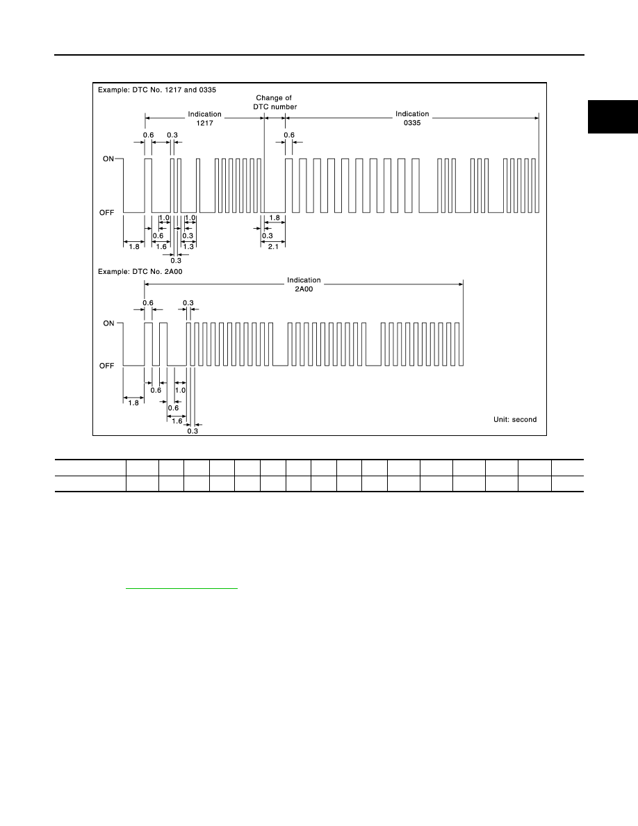
tified codes can be identified by using the CONSULT-III or GST. A DTC will be used as an example for how to

read a code.

A particular trouble code can be identified by the number of four-digit numeral flashes as follows.

The length of time the 1,000th-digit numeral flashes on and off is 1.2 seconds consisting of an ON (0.6-sec-

ond) - OFF (0.6-second) cycle.

The 100th-digit numeral and lower digit numerals consist of a 0.3-second ON and 0.3-second OFF cycle.

A change from one digit numeral to another occurs at an interval of 1.0-second OFF. In other words, the later

numeral appears on the display 1.3 seconds after the former numeral has disappeared.

A change from one trouble code to another occurs at an interval of 1.8-second OFF.

In this way, all the detected malfunctions are classified by their DTC numbers. The DTC 0000 refers to no mal-

function. (See 

EC-1015, "DTC Index"

)

How to Switch Diagnostic Test Mode

NOTE:

• It is better to count the time accurately with a clock.

• It is impossible to switch the diagnostic mode when an accelerator pedal position sensor circuit has

a malfunction.

• Always ECM returns to Diagnostic Test Mode I after ignition switch is turned OFF.

HOW TO SET DIAGNOSTIC TEST MODE II (SELF-DIAGNOSTIC RESULTS)

1. Confirm that accelerator pedal is fully released, turn ignition switch ON and wait 3 seconds.

2. Repeat the following procedure quickly five times within 5 seconds.

-

Fully depress the accelerator pedal.

-

Fully release the accelerator pedal.

3. Wait 7 seconds, fully depress the accelerator pedal and keep it for approx. 10 seconds until the MIL starts

blinking.

NOTE:

Do not release the accelerator pedal for 10 seconds if MIL may start blinking on the halfway of this

10 seconds. This blinking is displaying SRT status and is continued for another 10 seconds.

JMBIA1140GB

Number

0

1

2

3

4

5

6

7

8

9

A

B

C

D

E

F

Flashes

10

1

2

3

4

5

6

7

8

9

11

12

13

14

15

16

EC-650

< FUNCTION DIAGNOSIS >

[QR25DE EXCEPT FOR CALIFORNIA]

ON BOARD DIAGNOSTIC (OBD) SYSTEM

4. Fully release the accelerator pedal.

ECM has entered to Diagnostic Test Mode II (Self-diagnostic results).

NOTE:

Wait until the same DTC (or 1st trip DTC) appears to confirm all DTCs certainly.

HOW TO ERASE DIAGNOSTIC TEST MODE II (SELF-DIAGNOSTIC RESULTS)

1. Set ECM in Diagnostic Test Mode II (Self-diagnostic results). Refer to “”.

2. Fully depress the accelerator pedal and keep it for more than 10 seconds.

The emission-related diagnostic information has been erased from the backup memory in the ECM.

3. Fully release the accelerator pedal, and confirm the DTC 0000 is displayed.

OBD System Operation Chart

Relationship Between MIL, 1st Trip DTC, DTC and Detectable Items

• When a malfunction is detected for the first time, the 1st trip DTC and the 1st trip freeze frame data are

stored in the ECM memory.

• When the same malfunction is detected in two consecutive trips, the DTC and the freeze frame data are

stored in the ECM memory, and the MIL will come on.

• The MIL will go off after the vehicle is driven 3 times (driving pattern B) with no malfunction. The drive is

counted only when the recorded driving pattern is met (as stored in the ECM). If another malfunction occurs

while counting, the counter will reset.

• The DTC and the freeze frame data will be stored until the vehicle is driven 40 times (driving pattern A) with-

out the same malfunction recurring (except for Misfire and Fuel Injection System). For Misfire and Fuel Injec-

tion System, the DTC and freeze frame data will be stored until the vehicle is driven 80 times (driving pattern

C) without the same malfunction recurring. The “TIME” in “SELF-DIAGNOSTIC RESULTS” mode of CON-

SULT-III will count the number of times the vehicle is driven.

• The 1st trip DTC is not displayed when the self-diagnosis results in OK for the 2nd trip.

Summary Chart

For details about patterns B and C under “Fuel Injection System” and “Misfire”, see “EXPLANATION FOR DRIVING PATTERNS FOR
“MISFIRE <EXHAUST QUALITY DETERIORATION>”, “FUEL INJECTION SYSTEM”.
For details about patterns A and B under Other, see “EXPLANATION FOR DRIVING PATTERNS FOR “MISFIRE <EXHAUST QUALITY
DETERIORATION>”, “FUEL INJECTION SYSTEM”.
*1: Clear timing is at the moment OK is detected.
*2: Clear timing is when the same malfunction is detected in the 2nd trip.

Relationship Between MIL, DTC, 1st Trip DTC and Driving Patterns for “Misfire <Exhaust Quality Deterioration>”,
“Fuel Injection System”

PBIB0092E

Items

Fuel Injection System

Misfire

Other

MIL (goes off)

3 (pattern B)

3 (pattern B)

3 (pattern B)

DTC, Freeze Frame Data (no 
display)

80 (pattern C)

80 (pattern C)

40 (pattern A)

1st Trip DTC (clear)

1 (pattern C), *

1

1 (pattern C), *

1

1 (pattern B)

1st Trip Freeze Frame Data 
(clear)

*1, *2

*1, *2

1 (pattern B)

ON BOARD DIAGNOSTIC (OBD) SYSTEM

EC-651

< FUNCTION DIAGNOSIS >

[QR25DE EXCEPT FOR CALIFORNIA]

C

D

E

F

G

H

I

J

K

L

M

A

EC

N

P

O

Explanation for Driving Patterns for “Misfire <Exhaust Quality Deterioration>”, “Fuel Injection System”

<Driving Pattern B>

Driving pattern B means the vehicle operation as follows:

All components and systems should be monitored at least once by the OBD system.

*1: When the same malfunction is de-

tected in two consecutive trips, MIL 
will light up.

*2: MIL will go off after vehicle is driven 3 

times (pattern B) without any mal-
functions.

*3: When the same malfunction is de-

tected in two consecutive trips, the 
DTC and the freeze frame data will be 
stored in ECM.

*4: The DTC and the freeze frame data 

will not be displayed any longer after 
vehicle is driven 80 times (pattern C) 
without the same malfunction. (The 
DTC and the freeze frame data still 
remain in ECM.)

*5: When a malfunction is detected for 

the first time, the 1st trip DTC and the 
1st trip freeze frame data will be 
stored in ECM.

*6: The 1st trip DTC and the 1st trip 

freeze frame data will be cleared at 
the moment OK is detected.

*7: When the same malfunction is de-

tected in the 2nd trip, the 1st trip 
freeze frame data will be cleared.

*8: 1st trip DTC will be cleared when ve-

hicle is driven once (pattern C) with-
out the same malfunction after DTC 
is stored in ECM.

SEF392S

EC-652

< FUNCTION DIAGNOSIS >

[QR25DE EXCEPT FOR CALIFORNIA]

ON BOARD DIAGNOSTIC (OBD) SYSTEM

• The B counter will be cleared when the malfunction is detected once regardless of the driving pattern.

• The B counter will be counted up when driving pattern B is satisfied without any malfunction.

• The MIL will go off when the B counter reaches 3. (*2 in “OBD SYSTEM OPERATION CHART”)

<Driving Pattern C>

Driving pattern C means the vehicle operation as follows:

The following conditions should be satisfied at the same time:

Engine speed: (Engine speed in the freeze frame data) 

±375 rpm

Calculated load value: (Calculated load value in the freeze frame data) x (1

±0.1) [%]

Engine coolant temperature (T) condition:

• When the freeze frame data shows lower than 70

°C (158°F), T should be lower than 70°C (158°F).

• When the freeze frame data shows higher than or equal to 70

°C (158°F), T should be higher than or equal to

70

°C (158°F).

Example:

If the stored freeze frame data is as follows:

Engine speed: 850 rpm, Calculated load value: 30%, Engine coolant temperature: 80

°C (176°F)

To be satisfied with driving pattern C, the vehicle should run under the following conditions:

Engine speed: 475 - 1,225 rpm, Calculated load value: 27 - 33%, Engine coolant temperature: more than 70

°C

(158

°F)

• The C counter will be cleared when the malfunction is detected regardless of vehicle conditions above.

• The C counter will be counted up when vehicle conditions above is satisfied without the same malfunction.

• The DTC will not be displayed after C counter reaches 80.

• The 1st trip DTC will be cleared when C counter is counted once without the same malfunction after DTC is

stored in ECM.

Relationship Between MIL, DTC, 1st Trip DTC and Driving Patterns Except For “Misfire <Exhaust Quality Deteriora-
tion>”, “Fuel Injection System”


Content   ..  380  381  382  383   ..