Content .. 1487 1488 1489 1490 ..
Nissan Altima L32. Manual - part 1489
TM-300
< FUNCTION DIAGNOSIS >
[CVT: RE0F10A]
DIAGNOSIS SYSTEM (TCM)
SOLMON1 (A)
X
X
Torque converter clutch solenoid valve monitor
current
SOLMON2 (A)
X
X
Pressure control solenoid valve A (line pressure
solenoid valve) monitor current
SOLMON3 (A)
X
X
Pressure control solenoid valve B (secondary
pressure solenoid valve) monitor current
P POSITION SW (On/Off)
X
—
—
R POSITION SW (On/Off)
X
—
—
N POSITION SW (On/Off)
X
—
—
D POSITION SW (On/Off)
X
—
—
L POSITION SW (On/Off)
X
—
—
BRAKE SW (On/Off)
X
X
Stop lamp switch (Signal input with CAN commu-
nications)
FULL SW (On/Off)
X
X
Signal input with CAN communications
IDLE SW (On/Off)
X
X
SPORT MODE SW (On/Off)
X
X
STRDWNSW (On/Off)
X
—
Not mounted but displayed.
STRUPSW (On/Off)
X
—
DOWNLVR (On/Off)
X
—
UPLVR (On/Off)
X
—
NONMMODE (On/Off)
X
—
MMODE (On/Off)
X
—
INDLRNG (On/Off)
—
—
—
INDDRNG (On/Off)
—
—
“D” position indicator output
INDNRNG (On/Off)
—
—
“N” position indicator output
INDRRNG (On/Off)
—
—
“R” position indicator output
INDPRNG (On/Off)
—
—
“P” position indicator output
CVT LAMP (On/Off)
—
—
—
SPORT MODE IND (On/Off)
—
—
—
MMODE IND (On/Off)
—
—
—
SMCOIL D (On/Off)
—
—
Step motor coil “D” energizing status
SMCOIL C (On/Off)
—
—
Step motor coil “C” energizing status
SMCOIL B (On/Off)
—
—
Step motor coil “B” energizing status
SMCOIL A (On/Off)
—
—
Step motor coil “A” energizing status
LUSEL SOL OUT (On/Off)
—
—
—
REV LAMP (On/Off)
—
X
—
LUSEL SOL MON (On/Off)
—
—
—
VDC ON (On/Off)
X
—
—
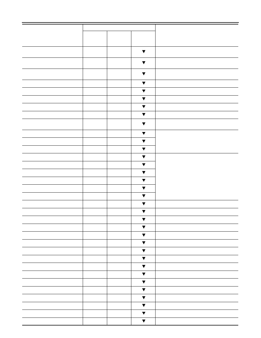
Monitored item (Unit)
Monitor item selection
Remarks
ECU INPUT
SIGNALS
MAIN SIG-
NALS
SELEC-
TION FROM
MENU