Content .. 1446 1447 1448 1449 ..
Nissan Altima L32. Manual - part 1448
TM-136
< COMPONENT DIAGNOSIS >
[CVT: RE0F09B]
P0715 INPUT SPEED SENSOR (PRI SPEED SENSOR)
1. Start engine.
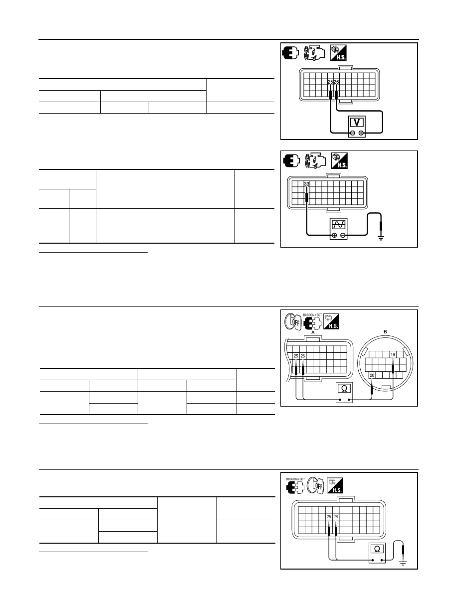
2. Check voltage between TCM harness connector F16 terminal
25 and 26.
3. If OK, check the pulse when vehicle cruises.
Is the inspection result normal?
OK
>> GO TO 7.
NG - 1 >> Battery voltage is not supplied: GO TO 2.
NG - 2 >> Battery voltage is supplied, but there is a malfunction in the frequency: GO TO 4.
2.
CHECK HARNESS BETWEEN TCM AND CVT UNIT HARNESS CONNECTOR (SENSOR POWER AND
SENSOR GROUND) (PART 1)
1. Turn ignition switch OFF.
2. Disconnect TCM harness connector and CVT unit harness con-
nector.
3. Check continuity between TCM harness connector F16 (A) ter-
minal 25 and 26 and CVT unit harness connector F46 (B) termi-
nal 19 and 20.
Is the inspection result normal?
YES
>> GO TO 3.
NO
>> Repair or replace damaged parts.
3.
CHECK HARNESS BETWEEN TCM AND CVT UNIT HARNESS CONNECTOR (SENSOR POWER AND
SENSOR GROUND) (PART 2)
Check continuity between TCM harness connector F16 terminal 25
and 26 and ground.
Is the inspection result normal?
YES
>> GO TO 6.
TCM harness connector
Data (Approx.)
Connector
Terminal
F16
25
26
5.0 V
JPDIA0981ZZ
TCM harness
connector
Condition
Voltage
(Approx.)
Con-
nector
Termi-
nal
F16
33
When running at 20 km/h (12 MPH) in “M
1
” po-
sition with the closed throttle position signal
OFF, use the CONSULT-III pulse frequency
measuring function.
660 Hz
JPDIA0989ZZ
TCM harness connector
CVT unit harness connector
Continuity
Connector
Terminal
Connector
Terminal
F16 (A)
25
F46 (B)
19
Existed
26
20
Existed
AWDIA0101ZZ
TCM harness connector
Ground
Continuity
Connector
Terminal
F16
25
Not existed
26
AWDIA0102ZZ