Nissan Titan. Manual - part 20
EBD
BRC-21
< SYSTEM DESCRIPTION >
[VDC/TCS/ABS]
C
D
E
G
H
I
J
K
L
M
A
B
BRC
N
O
P
EBD
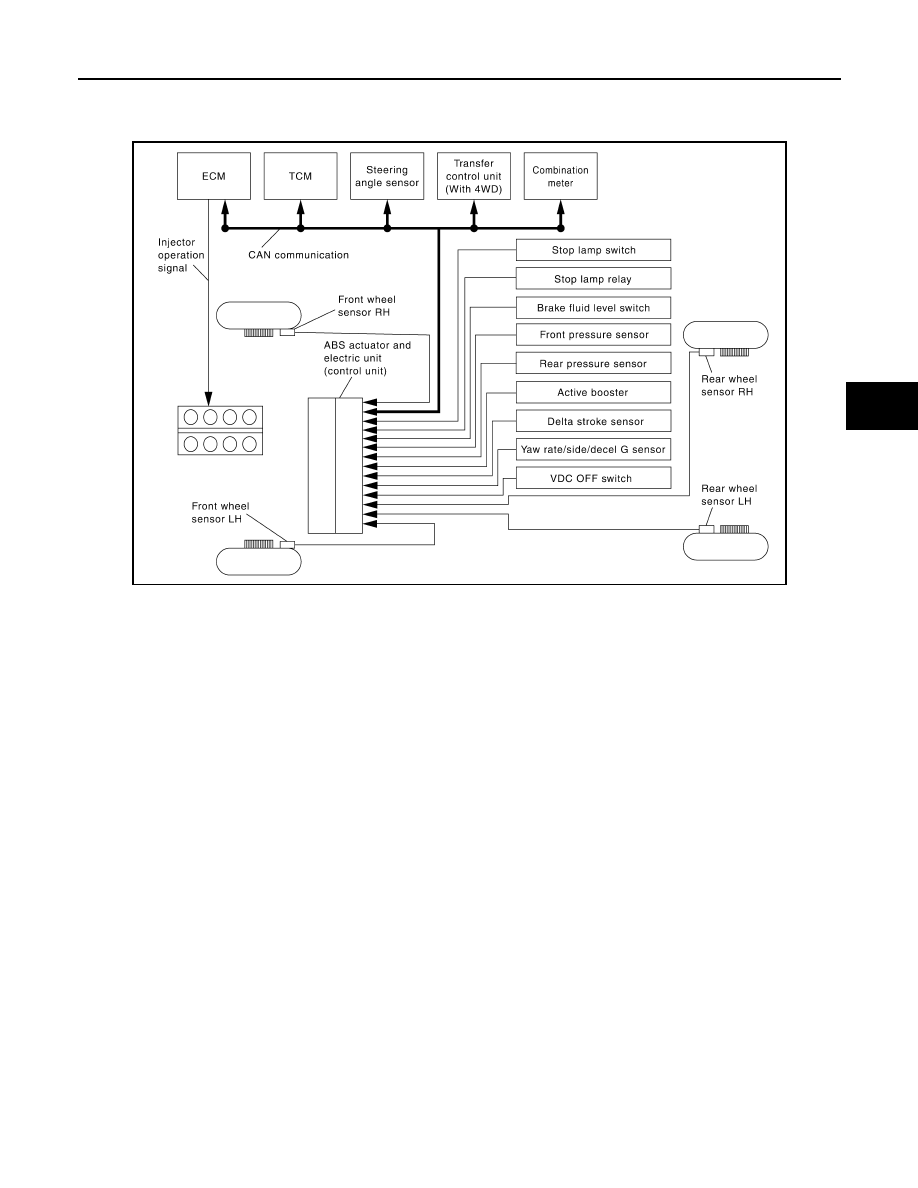
System Diagram
INFOID:0000000009883599
System Description
INFOID:0000000009883600
• Electric Brake force Distribution is a following function. ABS actuator and electric unit (control unit) detects
subtle slippages between the front and rear wheels during braking. Then it electronically controls the rear
braking force (brake fluid pressure) to reduce rear wheel slippage. Accordingly, it improves vehicle stability.
• Electrical system diagnosis by CONSULT is available.
AWFIA0461GB