Nissan Note E12. Manual - part 555


  Index      Nissan     Nissan Note E12 - Service and Repair Manual


Search            


Content   ..  553  554  555  556   ..


Nissan Note E12. Manual - part 555


SEC-72

< DTC/CIRCUIT DIAGNOSIS >

B2555 STOP LAMP

3.

CHECK STOP LAMP SWITCH INPUT SIGNAL 2

1. Connect stop lamp switch connector.

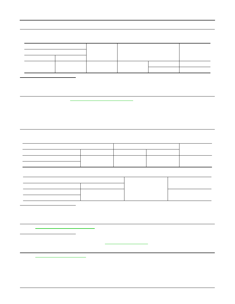
2. Check voltage between BCM harness connector and ground.

Is the inspecting result normal?

YES

>> GO TO 4.

NO

>> GO TO 5.

4.

REPLACE BCM

1. Replace BCM. Refer to 

BCS-67, "Removal and Installation"

.

2. Perform initialization of BCM and registration of all Intelligent Keys using CONSULT. Refer to the CON-

SULT Immobilizer mode and follow the on-screen instructions.

>> Inspection End.

5.

CHECK STOP LAMP SWITCH CIRCUIT

1. Disconnect stop lamp switch connector.

2. Check continuity between stop lamp switch harness connector and BCM harness connector.

3. Check continuity between stop lamp switch harness connector and ground.

Is the inspection result normal?

YES

>> GO TO 6.

NO

>> Repair or replace harness.

6.

CHECK STOP LAMP SWITCH

Refer to 

SEC-72, "Component Inspection"

.

Is the inspection result normal?

YES

>> GO TO 7.

NO

>> Replace stop lamp switch. Refer to 

BR-19, "Exploded View"

.

7.

CHECK INTERMITTENT INCIDENT

Refer to 

GI-41, "Intermittent Incident"

.

>> Inspection End.

Component Inspection

INFOID:0000000009567428

1.

CHECK STOP LAMP SWITCH

1. Turn ignition switch OFF.

(+)

(–)

Condition

Voltage (V)

(Approx.)

BCM

Connector

Terminal

M18

9

Ground

Brake pedal

Depressed

Battery voltage

Not depressed

0

Stop lamp switch

BCM

Continuity

Connector

Terminal

Connector

Terminal

E13 (CVT)

2

M18

9

Yes

E57 (MT)

Stop lamp switch

Ground

Continuity

Connector

Terminal

E13 (CVT)

2

No

E57 (MT)

B2555 STOP LAMP

SEC-73

< DTC/CIRCUIT DIAGNOSIS >

C

D

E

F

G

H

I

J

L

M

A

B

SEC

N

O

P

2. Disconnect stop lamp switch connector.

3. Check continuity between stop lamp switch terminals.

Is the inspection result normal?

YES

>> Inspection End.

NO

>> Replace stop lamp switch. Refer to 

BR-19, "Exploded View"

.

Stop lamp switch

Condition

Continuity

Terminal

1

2

Brake pedal

Not depressed

No

Depressed

Yes

SEC-74

< DTC/CIRCUIT DIAGNOSIS >

B2556 PUSH-BUTTON IGNITION SWITCH

B2556 PUSH-BUTTON IGNITION SWITCH

DTC Logic

INFOID:0000000009567429

DTC DETECTION LOGIC

DTC CONFIRMATION PROCEDURE

1.

PERFORM DTC CONFIRMATION PROCEDURE

1. Press push-button ignition switch under the following condition.

-

Brake pedal: Not depressed

2. Release push-button ignition switch and wait 100 seconds or more.

3. Check DTC in Self Diagnostic Result mode of BCM using CONSULT.
Is DTC detected?

YES

>> Go to 

SEC-74, "Diagnosis Procedure"

.

NO

>> Inspection End.

Diagnosis Procedure

INFOID:0000000009567430

Regarding Wiring Diagram information, refer to 

SEC-24, "Wiring Diagram"

.

1.

CHECK PUSH-BUTTON IGNITION SWITCH INPUT SIGNAL

1. Turn ignition switch OFF.

2. Disconnect push-button ignition switch connector.

3. Check voltage between push-button ignition switch harness connector and ground.

Is the inspection result normal?

YES

>> GO TO 4.

NO

>> GO TO 2.

2.

CHECK PUSH-BUTTON IGNITION SWITCH CIRCUIT

1. Disconnect BCM connector and IPDM E/R connector.

2. Check continuity between push-button ignition switch harness connector and BCM harness connector.

3. Check continuity between push-button ignition switch harness connector and ground.

DTC No.

Trouble diagnosis name

DTC detecting condition

Possible cause

B2556

ENG START SW

BCM detects the push-button ignition switch 
stuck at ON for 100 seconds or more.

• Harness or connectors

(Push-button ignition switch circuit is 
shorted.)

• Push-button ignition switch
• BCM

(+)

(–)

Voltage (V)

(Approx.)

Push-button ignition switch

Connector

Terminal

M25

8

Ground

12

Push-button ignition switch

BCM

Continuity

Connector

Terminal

Connector

Terminal

M25

8

M98

76

Yes

Push-button ignition switch

Ground

Continuity

Connector

Terminal

M25

8

No

B2556 PUSH-BUTTON IGNITION SWITCH

SEC-75

< DTC/CIRCUIT DIAGNOSIS >

C

D

E

F

G

H

I

J

L

M

A

B

SEC

N

O

P

Is the inspection result normal?

YES

>> GO TO 3.

NO

>> Repair or replace harness.

3.

REPLACE BCM

1. Replace BCM. Refer to 

BCS-67, "Removal and Installation"

.

2. Perform initialization of BCM and registration of all Intelligent Keys using CONSULT. Refer to the CON-

SULT Immobilizer mode and follow the on-screen instructions.

>> Inspection End.

4.

CHECK PUSH-BUTTON IGNITION SWITCH GROUND CIRCUIT

Check continuity between push-button ignition switch harness connector and ground.

Is the inspection result normal?

YES

>> GO TO 5.

NO

>> Repair or replace harness.

5.

CHECK PUSH-BUTTON IGNITION SWITCH

Refer to 

SEC-75, "Component Inspection"

.

Is the inspection result normal?

YES

>> GO TO 6.

NO

>> Replace push-button ignition switch. Refer to 

SEC-122, "Removal and Installation"

.

6.

CHECK INTERMITTENT INCIDENT

Refer to 

GI-41, "Intermittent Incident"

.

>> Inspection End.

Component Inspection

INFOID:0000000009567431

1.

CHECK PUSH-BUTTON IGNITION SWITCH

1. Turn ignition switch OFF.

2. Disconnect push-button ignition switch connector.

3. Check continuity between push-button ignition switch terminals.

Is the inspection result normal?

YES

>> Inspection End.

NO

>> Replace push-button ignition switch. Refer to 

SEC-122, "Removal and Installation"

.

Push-button ignition switch

Ground

Continuity

Connector

Terminal

M25

4

Yes

Push-button ignition switch

Condition

Continuity

Terminal

4

8

Push-button ignition 
switch

Pressed

Yes

Not pressed

No


Content   ..  553  554  555  556   ..