Nissan Note E12. Manual - part 456


  Index      Nissan     Nissan Note E12 - Service and Repair Manual


Search            


Content   ..  454  455  456  457   ..


Nissan Note E12. Manual - part 456


MWI-10

< SYSTEM DESCRIPTION >

SYSTEM

SHIFT POSITION INDICATOR : System Description

INFOID:0000000009549337
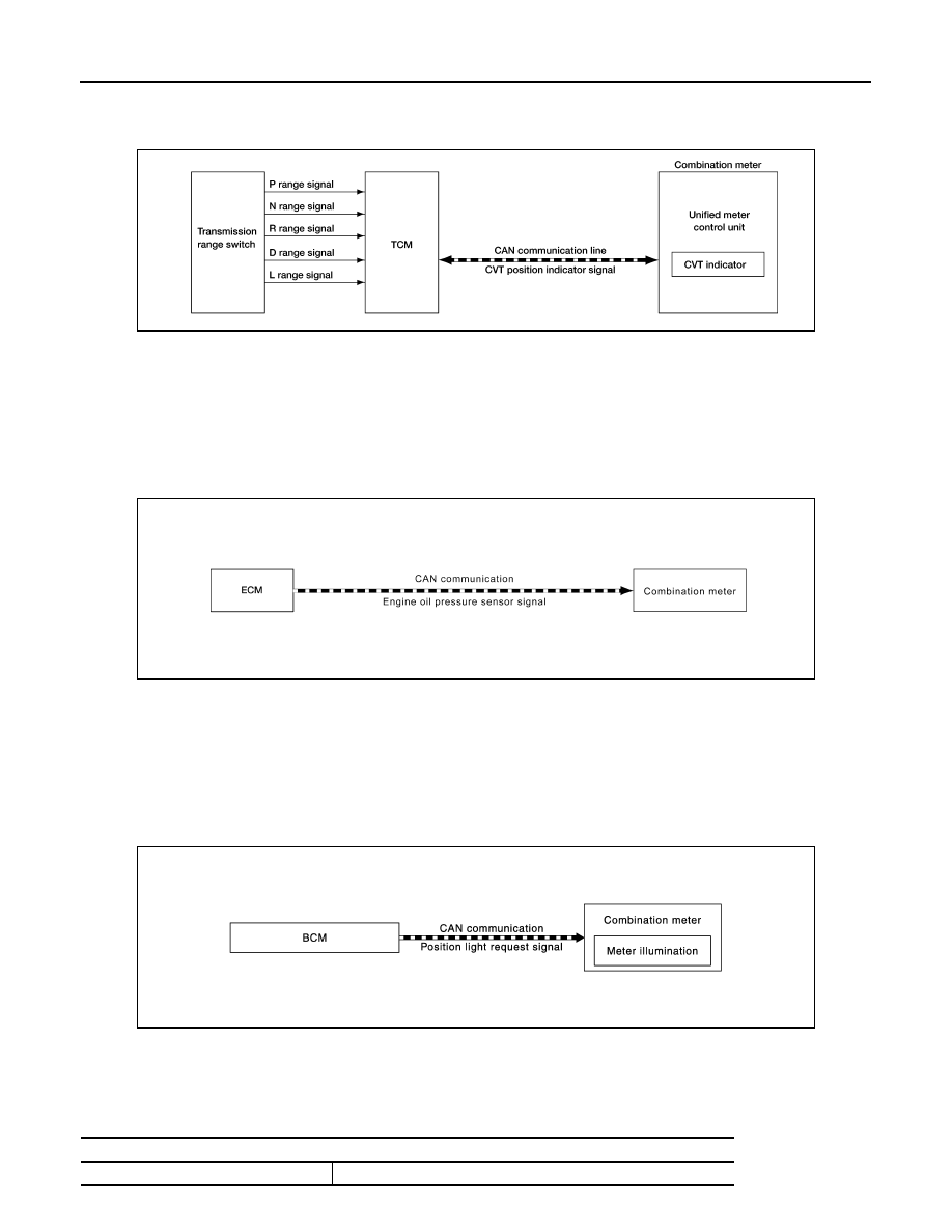
SYSTEM DIAGRAM

DESCRIPTION

The combination meter receives the shift position signal from TCM via CAN communication, and displays the

position of the shift indicator.

OIL PRESSURE WARNING LAMP
OIL PRESSURE WARNING LAMP : System Description

INFOID:0000000009549339

SYSTEM DIAGRAM

DESCRIPTION

The combination meter turns the engine oil pressure warning lamp ON when receiving a signal from the ECM

via CAN communication.

METER ILLUMINATION CONTROL
METER ILLUMINATION CONTROL : System Description

INFOID:0000000009549341

SYSTEM DIAGRAM

DESCRIPTION

• Combination meter controls meter illumination, based on the following signal.

- Position light request signal

• The combination meter turns ON meter illumination when the following conditions are satisfied.

AWNIA3081GB

AWNIA2885GB

JSNIA2919GB

Condition

Combination switch (Lighting switch)

1st or 2nd position

MWI

SYSTEM

MWI-11

< SYSTEM DESCRIPTION >

C

D

E

F

G

H

I

J

K

L

M

B

A

O

P

• The combination meter turns OFF meter illumination when the following conditions are satisfied.

INFORMATION DISPLAY
INFORMATION DISPLAY : System Description

INFOID:0000000009549343

SYSTEM DIAGRAM

DESRIPTION

• The combination meter receives signals from switches, sensors and modules for operating the following

functions on  the information display.

- Odo/trip meter

- Engine coolant temperature gauge

- Fuel gauge

- Trip computer

- Interrupt indication

- Meter illumination level

- Low fuel warning

- Loose fuel cap warning

ODO/TRIP METER

The combination meter calculates mileage using the vehicle speed signal from the ABS actuator and electric

unit (control unit) and displays the mileage on the information display.

ENGINE COOLANT TEMPERATURE GAUGE

The engine coolant temperature gauge indicates the engine coolant temperature.

The ECM provides an engine coolant temperature signal to the combination meter  via CAN communication. 

FUEL GAUGE

Control Outline

The fuel level sensor unit sends a variable resistor signal to the combination meter. The fuel gauge indicates

the approximate fuel level in the fuel tank. 

Refuel Control

The unit detects the driver is refueling the vehicle and accelerates the fuel gauge segment movement if the
fuel level changes by 9   (2-3/8 US, 2 lmp gal) or more.

Condition

Combination switch (Lighting switch)

OFF

AWNIA2439GB

MWI-12

< SYSTEM DESCRIPTION >

SYSTEM

Lighting segment-resistance relationship

INTERRUPT INDICATION

Low Fuel Warning

The low fuel warning turns ON when the fuel level in the fuel tank reaches approximately 7.3   (1-7/8 US gal,

1-5/8 Imp gal).

LOOSE FUEL CAP WARNING

The LOOSE FUEL CAP message will display in the information display when the fuel-filler cap is not tightened

correctly. The message will turn off as soon as the ECM detects the fuel-filler cap is properly tightened. The

ECM provides a loose fuel cap signal to the combination meter via CAN communication lines.

AWNIA3088GB

MWI

OPERATION

MWI-13

< SYSTEM DESCRIPTION >

C

D

E

F

G

H

I

J

K

L

M

B

A

O

P

OPERATION

Switch Name and Function

INFOID:0000000009643045

JSNIA3909ZZ

Switch name

Operation

Description

Illumination control switch (1)

Press

An illuminance level of the back light of the combination meter can be adjusted.

Meter control switch (2) 

• The information display screen can be switched.
• The trip meter can be switched between A and B.
• Trip meter A/B can be reset by pressing and holding the meter control switch.
• Time can be adjusted.


Content   ..  454  455  456  457   ..