Nissan Note E12. Manual - part 336
FRONT COIL SPRING AND STRUT
FSU-9
< REMOVAL AND INSTALLATION >
C
D
F
G
H
I
J
K
L
M
A
B
FSU
N
O
P
REMOVAL AND INSTALLATION
FRONT COIL SPRING AND STRUT
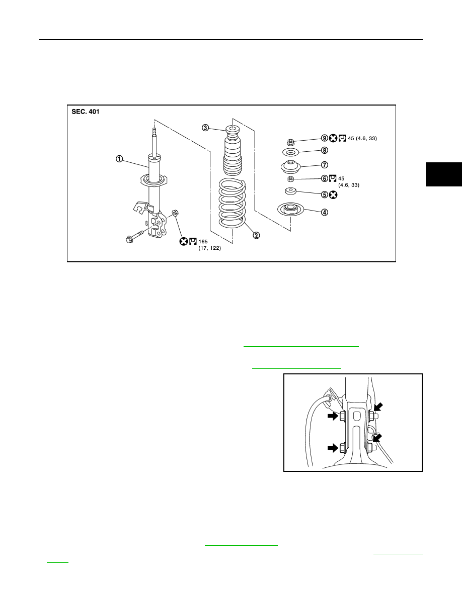
Exploded View
INFOID:0000000009578932
Removal and Installation
INFOID:0000000009578933
REMOVAL
1. Remove the wheel and tire using power tool. Refer to
WT-8, "Removal and Installation"
.
2. Remove brake hose lock plate from strut.
3. Disconnect stabilizer connecting rod from strut. Refer to
.
4. Remove strut bolts and nuts from steering knuckle.
5. Remove stopper insulator lock nut and stopper insulator.
6. Remove strut.
INSTALLATION
Installation is in the reverse order of removal.
• Secure the head of strut piston rod to keep it from rotating, then tighten the stopper insulator lock nut to the
specified torque.
CAUTION:
• Do not reuse stopper insulator lock nut.
• Do not reuse the nuts that secure the strut to the steering knuckle.
• Perform inspection after installation. Refer to
.
• After replacing the strut, always follow the disposal procedure to discard the strut. Refer to
1.
Strut
2.
Coil spring
3.
Bound bumper
4.
Spring upper seat
5.
Strut mount bearing
6.
Piston rod lock nut
7.
Strut mount insulator
8.
Stopper insulator
9.
Stopper insulator lock nut
JPEIA0261GB
WEIA0179E