Nissan Note E12. Manual - part 236


  Index      Nissan     Nissan Note E12 - Service and Repair Manual


Search            


Content   ..  234  235  236  237   ..


Nissan Note E12. Manual - part 236


P2101 ELECTRIC THROTTLE CONTROL FUNCTION

EC-283

< DTC/CIRCUIT DIAGNOSIS >

[HR16DE]

C

D

E

F

G

H

I

J

K

L

M

A

EC

N

P

O

P2101 ELECTRIC THROTTLE CONTROL FUNCTION

DTC Logic

INFOID:0000000009022646

DTC DETECTION LOGIC

NOTE:

• If DTC P2101 is displayed with DTC P2100, first perform the trouble diagnosis for DTC P2100. Refer

to 

EC-280, "DTC Logic"

.

• If DTC P2101 is displayed with DTC P2119, first perform the trouble diagnosis for DTC P2119. Refer

to 

EC-289, "DTC Logic"

.

DTC CONFIRMATION PROCEDURE

1.

PRECONDITIONING

If DTC Confirmation Procedure has been previously conducted, always perform the following before conduct-

ing the next test. 

1. Turn ignition switch OFF and wait at least 10 seconds.

2. Turn ignition switch ON.

3. Turn ignition switch OFF and wait at least 10 seconds.

TESTING CONDITION:

Before performing the following procedure, confirm that battery voltage is more than 11 V when

engine is running.

>> GO TO 2.

2.

PERFORM DTC CONFIRMATION PROCEDURE

1. Turn ignition switch ON and wait at least 2 seconds.

2. Start engine and let it idle for 5 seconds.

3. Check DTC.
Is DTC detected?

YES

>> Proceed to 

EC-283, "Diagnosis Procedure"

.

NO

>> INSPECTION END

Diagnosis Procedure

INFOID:0000000009022647

1.

CHECK GROUND CONNECTION

1. Turn ignition switch OFF.

2. Check ground connection E15. Refer to Ground Inspection in 

GI-44, "Circuit Inspection"

Is the inspection result normal?

YES

>> GO TO 2.

NO

>> Repair or replace ground connection.

2.

CHECK THROTTLE CONTROL MOTOR RELAY INPUT SIGNAL CIRCUIT

1. Turn ignition switch ON.

2. Check the voltage between ECM harness connector and ground.
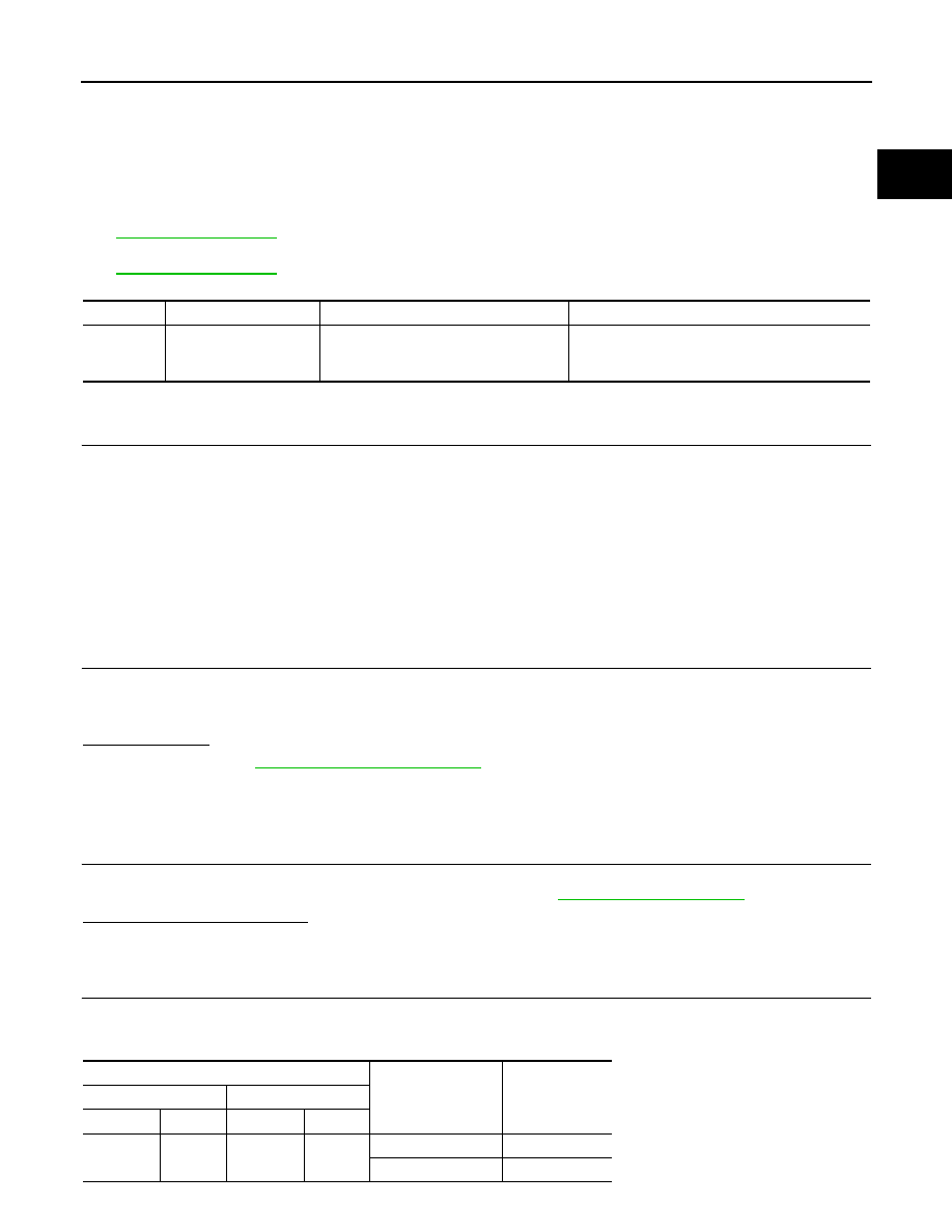
DTC No.

Trouble diagnosis name

DTC detecting condition

Possible cause

P2101

Electric throttle control 
performance

Electric throttle control function does not 
operate properly.

• Harness or connectors

(Throttle control motor circuit is open or shorted)

• Electric throttle control actuator

ECM

Condition

Voltage

+

Connector

Terminal

Connector

Terminal

F10

2

E16

108

Ignition switch OFF

Approx. 0 V

Ignition switch ON

Battery voltage

EC-284

< DTC/CIRCUIT DIAGNOSIS >

[HR16DE]

P2101 ELECTRIC THROTTLE CONTROL FUNCTION

Is the inspection result normal?

YES

>> GO TO 10.

NO

>> GO TO 3.

3.

CHECK THROTTLE CONTROL MOTOR RELAY POWER SUPPLY CIRCUIT-I

1. Turn ignition switch OFF.

2. Check voltage between ECM harness connector and ground.

Is the inspection result normal?

YES

>> GO TO 7.

NO

>> GO TO 4.

4.

CHECK THROTTLE CONTROL MOTOR RELAY POWER SUPPLY CIRCUIT-II

1. Disconnect ECM harness connector.

2. Disconnect IPDM E/R harness connector F42.

3. Check the continuity between ECM harness connector and IPDM E/R harness connector.

4. Also check harness for short to ground and short to power.
Is the inspection result normal?

YES

>> GO TO 6.

NO

>> GO TO 5.

5.

DETECT MALFUNCTIONING PART

Check the following.

• IPDM E/R connector F42

• Harness for open or short between IPDM E/R and ECM

>> Repair open circuit or short to ground or short to power in harness or connectors.

6.

CHECK FUSE

1. Disconnect 20A fuse (No. 53) from IPDM E/R.

2. Check 20A fuse for blown.
Is the inspection result normal?

YES

>> GO TO 9.

NO

>> Replace 20A fuse.

7.

CHECK THROTTLE CONTROL MOTOR RELAY POWER SUPPLY CIRCUIT-III

1. Disconnect ECM harness connector.

2. Disconnect IPDM E/R harness connector F42.

3. Check the continuity between ECM harness connector and IPDM E/R harness connector.

4. Also check harness for short to ground and short to power.
Is the inspection result normal?

YES

>> GO TO 9.

ECM

Voltage

+

Connector

Terminal

Connector

Terminal

F10

15

E16

108

Battery voltage

IPDM E/R

ECM

Continuity

Connector

Terminal

Connector

Terminal

F42

32

F10

15

Existed

IPDM E/R

ECM

Continuity

Connector

Terminal

Connector

Terminal

F42

29

F10

2

Existed

P2101 ELECTRIC THROTTLE CONTROL FUNCTION

EC-285

< DTC/CIRCUIT DIAGNOSIS >

[HR16DE]

C

D

E

F

G

H

I

J

K

L

M

A

EC

N

P

O

NO

>> GO TO 8.

8.

DETECT MALFUNCTIONING PART

Check the following.

• IPDM E/R connector F42

• Harness for open or short between IPDM E/R and ECM

>> Repair open circuit or short to ground or short to power in harness or connectors.

9.

CHECK INTERMITTENT INCIDENT

Refer to 

GI-41, "Intermittent Incident"

.

Is the inspection result normal?

YES

>> Replace IPDM E/R. Refer to 

PCS-30, "Removal and Installation"

.

NO

>> Repair or replace harness or connectors.

10.

CHECK THROTTLE CONTROL MOTOR OUTPUT SIGNAL CIRCUIT FOR OPEN OR SHORT

1. Turn ignition switch OFF.

2. Disconnect electric throttle control actuator harness connector.

3. Disconnect ECM harness connector.

4. Check the continuity between electric throttle control actuator harness connector and ECM harness con-

nector.

5. Also check harness for short to ground and short to power.
Is the inspection result normal?

YES

>> GO TO 11.

NO

>> Repair or replace harness or connectors.

11.

CHECK ELECTRIC THROTTLE CONTROL ACTUATOR VISUALLY 

1. Remove the intake air duct. Refer to 

EM-26, "Exploded View"

.

2. Check if foreign matter is caught between the throttle valve 

and the housing.

Is the inspection result normal?

YES

>> GO TO 12.

NO

>> Remove the foreign matter and clean the electric throttle

control actuator inside, and then perform throttle valve

closed position learning. Refer to 

EC-114, "Work Proce-

dure"

.

12.

CHECK THROTTLE CONTROL MOTOR

Refer to 

EC-286, "Component Inspection"

.

Is the inspection result normal?

YES

>> GO TO 13.

NO

>> GO TO 14.

13.

CHECK INTERMITTENT INCIDENT

Refer to 

GI-41, "Intermittent Incident"

.

Is the inspection result normal?

Electric throttle control actuator

ECM

Continuity

Connector

Terminal

Connector

Terminal

F7 

5

F10

1

Not existed

4

Existed

6

1

Existed

4

Not existed

: Vehicle front

PBIB2974E

EC-286

< DTC/CIRCUIT DIAGNOSIS >

[HR16DE]

P2101 ELECTRIC THROTTLE CONTROL FUNCTION

YES

>> GO TO 14.

NO

>> Repair or replace harness or connectors.

14.

REPLACE ELECTRIC THROTTLE CONTROL ACTUATOR

Replace malfunction electric throttle control actuator. Refer to 

EM-28, "Exploded View"

.

>> INSPECTION END

Component Inspection

INFOID:0000000009022648

1.

CHECK THROTTLE CONTROL MOTOR

1. Disconnect electric throttle control actuator harness connector.

2. Check resistance between electric throttle control actuator terminals as follows.

Is the inspection result normal?

YES

>> INSPECTION END

NO

>> GO TO 2.

2.

REPLACE ELECTRIC THROTTLE CONTROL ACTUATOR

Replace electric throttle control actuator. Refer to 

EM-28, "Exploded View"

.

>> INSPECTION END

Terminals

Resistance [at 25

°C (77°F)]

5 and 6

Approx. 1 - 15 

Ω 


Content   ..  234  235  236  237   ..