Nissan Note E12. Manual - part 109


  Index      Nissan     Nissan Note E12 - Service and Repair Manual


Search            


Content   ..  107  108  109  110   ..


Nissan Note E12. Manual - part 109


CLUTCH MASTER CYLINDER

CL-13

< REMOVAL AND INSTALLATION >

C

E

F

G

H

I

J

K

L

M

A

B

CL

N

O

P

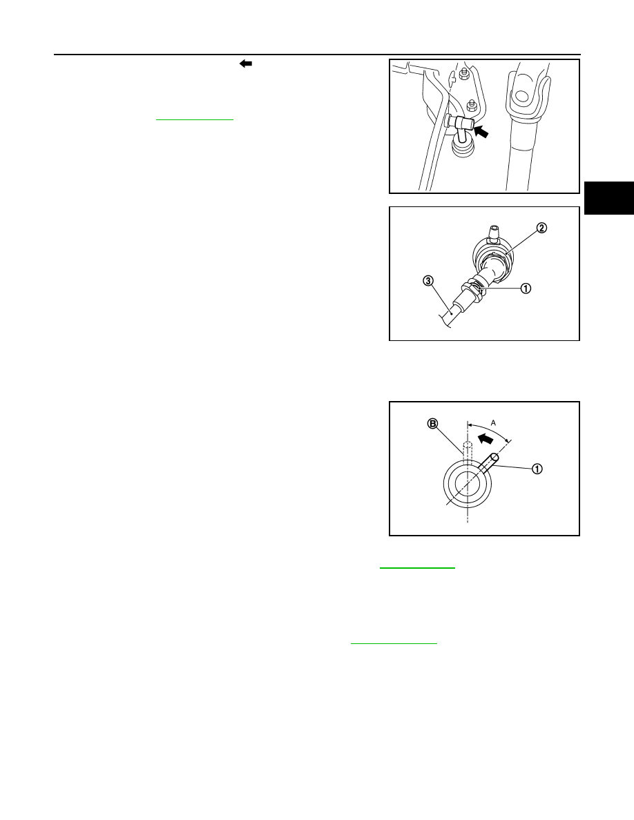
5. Remove master cylinder rod end (

) from clutch pedal.

6. Use one of the following methods to remove reservoir hose from

master cylinder.

• Drain clutch fluid from reservoir tank and remove reservoir

hose. Refer to 

CL-6, "Draining"

.

• Remove hose from master cylinder. 

7. Pull up the lock pin (1) from connector of master cylinder (2) and

separate clutch tube (3).

8. Rotate master cylinder clockwise by 45 degrees and then

remove master cylinder from the vehicle.

INSTALLATION

CAUTION:

Do not spill clutch fluid onto painted surfaces. If fluid spills, wipe up immediately and wash the

affected area with water.
1. With the nipple (1) rotated clockwise by 45 degrees, insert clutch

master cylinder into the mounting hole. Rotate the clutch master

cylinder counterclockwise by 45 degrees (A) as shown to secure

it. At this time, nipple is in the upward (B).

2. Install master cylinder rod end to clutch pedal.

CAUTION:

Press master cylinder rod end into clutch pedal until it

stops.

3. Install reservoir hose to master cylinder.
4. Press down the lock pin into connector of master cylinder until it

stops.

5. Install clutch tube into connector of master cylinder until it stops.
6. Fill with clutch fluid and bleed clutch hydraulic system. Refer to 

CL-7, "Refilling"

.

7. Installation of the remaining components is in the reverse order of removal.

Inspection and Adjustment

INFOID:0000000009417562

INSPECTION AFTER INSTALLATION

Check for clutch fluid leaks and check the fluid level. Refer to 

CL-6, "Inspection"

.

PCIB1491E

JPDIB0169ZZ

JPDIB0114ZZ

CL-14

< REMOVAL AND INSTALLATION >

CLUTCH PIPING

CLUTCH PIPING

Exploded View

INFOID:0000000009417563

Hydraulic Layout

INFOID:0000000009417564

Removal and Installation

INFOID:0000000009417565

CAUTION:

Do not spill clutch fluid onto painted surfaces. If clutch fluid spills, wipe up immediately and wash the

affected area with water.

NOTE:

When removing components such as hoses, tubes/lines, etc., cap or plug openings to prevent fluid from spill-

ing.

1.

CSC (Concentric Slave Cylinder)

2.

Clip

3.

Clutch tube

4.

Clutch damper

5.

Bracket

6.

Master cylinder

JPDIB0181ZZ

1.

Clutch tube

2.

Lock pin

3.

CSC (concentric slave cylinder)

4.

Clutch damper

5.

Master cylinder

6.

Clutch pedal

PCIB1499E

CLUTCH PIPING

CL-15

< REMOVAL AND INSTALLATION >

C

E

F

G

H

I

J

K

L

M

A

B

CL

N

O

P

REMOVAL 

1. Remove the battery. Refer to 

PG-69, "Removal and Installation (Battery)"

.

2. Use one of the following methods to remove hose from clutch master cylinder.

• Drain clutch fluid from reservoir tank and remove hose. Refer to 

CL-6, "Draining"

.

• Remove hose from clutch master cylinder.

3. Remove clutch tube lock pin from clutch master cylinder. 
4. Remove clutch tube lock pin at clutch housing.
5. Remove clutch tube lock pins (2) from clutch damper (3).
6. Remove clutch tube (1) from clutch damper (3).
7. Remove clutch damper (3) from bracket (4).

INSTALLATION

Installation is in the reverse order of removal.

CAUTION:

Do not damage clutch tube.

• Insert each clutch tube into the CSC bleeding connector, the clutch damper connector, and the clutch master

cylinder connector until it contacts the end of each connector.

• Install each lock pin into the clutch damper connector and the clutch master cylinder connector until it con-

tacts the end of each connector.

• After installation, bleed the air from the clutch hydraulic system. Refer to 

CL-8, "Air Bleeding"

.

Inspection and Adjustment

INFOID:0000000009417566

INSPECTION AFTER REMOVAL

• Check the clutch tube for cracks and damage. If the clutch tube has cracks or damage, replace it with a new

one.

• Check the O-ring of the clutch tube for cracks and damage. If the O-ring of the clutch tube has cracks or

damage, replace clutch tube with a new one.

• Check the clutch damper for cracks and damage. If the clutch damper has cracks or damage, replace it with

a new one.

INSPECTION AFTER INSTALLATION

Check for clutch fluid leaks and check the clutch fluid level. Refer to 

CL-6, "Inspection"

.

WCIA0597E

CL-16

< UNIT REMOVAL AND INSTALLATION >

CSC (CONCENTRIC SLAVE CYLINDER)

UNIT REMOVAL AND INSTALLATION

CSC (CONCENTRIC SLAVE CYLINDER)

Exploded View

INFOID:0000000009417567

Removal and Installation

INFOID:0000000009417568

CAUTION:

• Do not reuse CSC (concentric slave cylinder). CSC slides back to the original position every time

when removing transaxle assembly. At this time, dust on the sliding parts may damage the seal of

CSC and may cause clutch fluid leaks.

• Do not disassemble CSC.

• Do not spill clutch fluid onto painted surfaces. If clutch fluid spills, wipe up immediately and wash

the affected area with water.

NOTE:

When removing components such as hoses, tubes/lines, etc., cap or plug openings to prevent fluid from spill-

ing.

REMOVAL

1. Remove engine transaxle assembly. Refer to 

TM-23, "Removal and Installation"

.

2. Remove CSC bolts and the CSC from clutch housing.

INSTALLATION

1. Install CSC to clutch housing and then tighten CSC bolts to the specified torque.

CAUTION:

• Do not reuse CSC.

1.

Transaxle assembly

2.

CSC (concentric slave cylinder)

JPDIB0146GB

PCIB1498E


Content   ..  107  108  109  110   ..