Nissan Note E12. Manual - part 76
BR-40
< REMOVAL AND INSTALLATION >
REAR DRUM BRAKE
REAR DRUM BRAKE
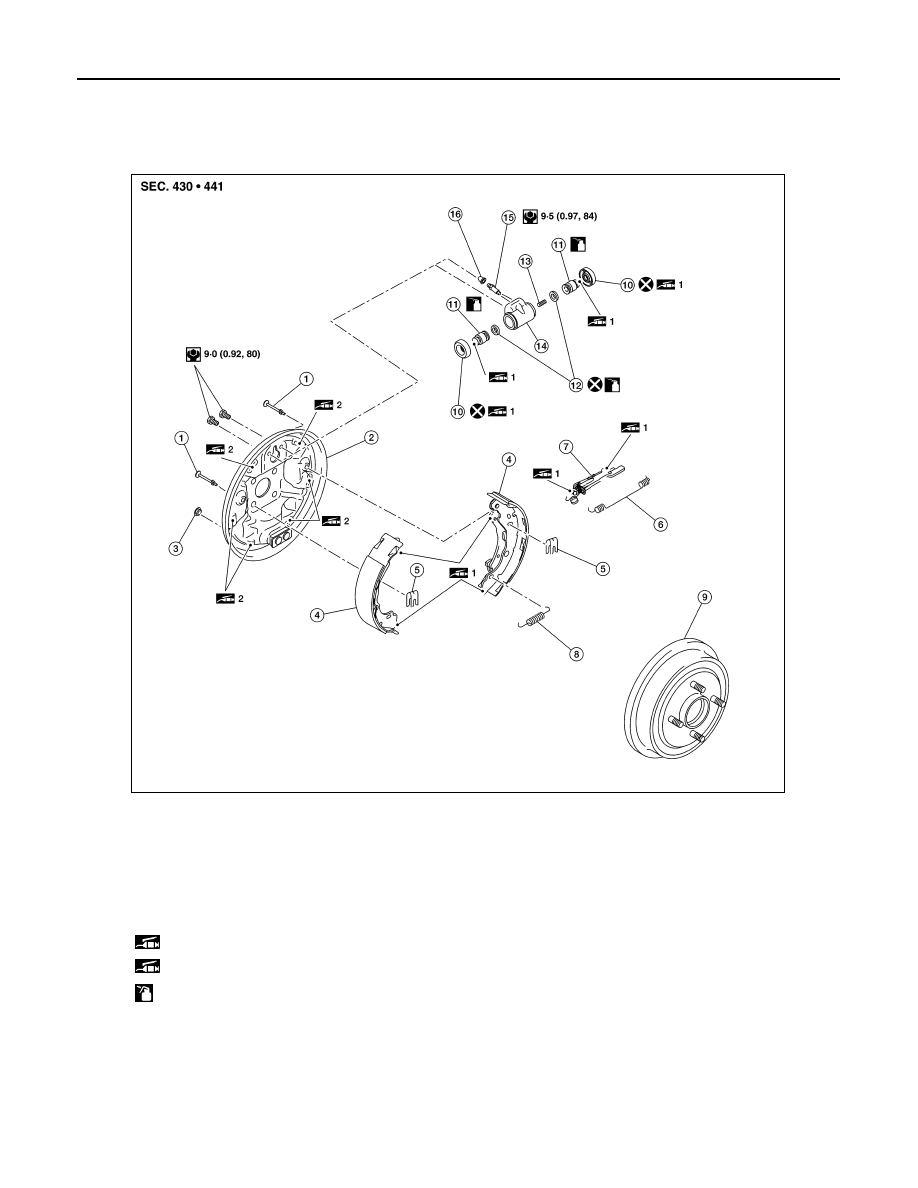
Exploded View
INFOID:0000000009365027
Removal and Installation
INFOID:0000000009365028
WARNING:
Clean any dust from the front brake and rear brake with a vacuum dust collector. Do not blow with
compressed air.
CAUTION:
• Do not depress the brake pedal while removing the brake drum because the pistons may pop out.
1.
Shoe hold pin
2.
Back plate
3.
Plug
4.
Brake shoe
5.
Retainer
6.
Upper spring
7.
Adjuster
8.
Return spring
9.
Brake drum
10. Boot
11. Piston
12.
Piston cup
13. Spring
14. Wheel cylinder
15.
Bleeder valve
16. Cap
1: Apply Syntheso® GLEP1 grease or equivalent.
2: Apply Molyguard GS 2039 grease or equivalent.
: Apply clean brake fluid
AWFIA1019ZZ