Nissan Note E12. Manual - part 29
AV-108
< SYSTEM DESCRIPTION >
[NAVIGATION]
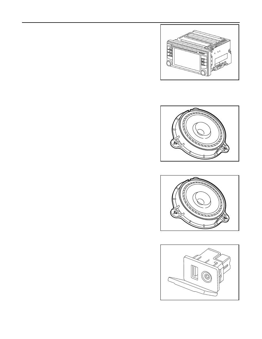
COMPONENT PARTS
• A 5.8-inch QVGA display, an AM/FM electronic tuner radio, CD
drive, audio amplifier, Bluetooth
®
module, USB interface, camera
controller and navigation unit are integrated into the AV control
unit.
• The 5.8-inch display is a high resolution monitor that includes
touch panel functions.
• Music files stored in iPod
®*
/USB memory can be played using the
separate USB interface.
Speaker
INFOID:0000000009606269
FRONT DOOR SPEAKER
• 16.5 cm (6.5 in) speakers are installed in the bottom of the front doors.
• Sound signals are input from the AV control unit to output high, mid
and low range sounds.
REAR DOOR SPEAKER
• 16.5 cm (6.5 in) speakers are installed in the bottom of the rear doors.
• Sound signals are input from the AV control unit to output high, mid
and low range sounds.
USB Interface and AUX In Jack
INFOID:0000000009606270
• USB Interface and AUX in jack is installed in the console.
• iPod
®
and USB memory can be connected to the AV control unit
through the USB interface.
• An external audio device can be connected to the AV control unit
through the AUX in jack.
ALNIA1524ZZ
JPNIA1454ZZ
JPNIA1454ZZ
ALNIA1523ZZ