Nissan Maxima. Manual - part 937


  Index      Nissan     Nissan Maxima (2009-2014 year) - Service and Repair Manual


Search            


Content   ..  935  936  937  938   ..


Nissan Maxima. Manual - part 937


DOOR KEY CYLINDER SWITCH

PWC-45

< DTC/CIRCUIT DIAGNOSIS >

[LH&RH FRONT WINDOW ANTI-PINCH]

C

D

E

F

G

H

I

J

L

M

A

B

PWC

N

O

P

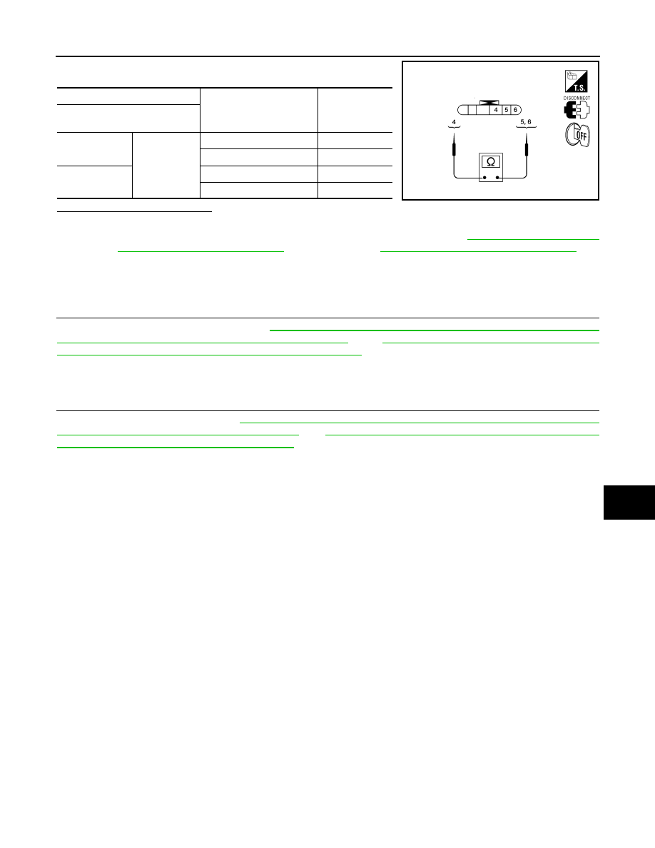
Check front door lock assembly LH (key cylinder switch).

Is the inspection result normal?

YES

>> Key cylinder switch is OK.

NO

>> Replace front door lock assembly LH (key cylinder switch). Refer to 

DLK-221, "FRONT DOOR

LOCK : Removal and Installation"

. After that, refer to 

PWC-45, "Special Repair Requirement"

.

Special Repair Requirement

INFOID:0000000010051243

1.

 PERFORM INITIALIZATION PROCEDURE

Perform initialization procedure. Refer to 

PWC-7, "ADDITIONAL SERVICE WHEN REMOVING BATTERY

NEGATIVE TERMINAL : Special Repair Requirement"

 and 

PWC-7, "ADDITIONAL SERVICE WHEN

REPLACING CONTROL UNIT : Special Repair Requirement"

.

>> GO TO 2

2.

 CHECK ANTI-PINCH OPERATION

Check anti-pinch operation. Refer to 

PWC-7, "ADDITIONAL SERVICE WHEN REMOVING BATTERY NEGA-

TIVE TERMINAL : Special Repair Requirement"

 and 

PWC-7, "ADDITIONAL SERVICE WHEN REPLACING

CONTROL UNIT : Special Repair Requirement"

.

>> End.

Terminal

Key position

Continuity

Front door lock assembly LH (key 

cylinder switch) connector

4

Unlock

Yes

Neutral / Lock

No

6

Lock

Yes

Neutral / Unlock

No

ALKIA0351ZZ

PWC-46

< DTC/CIRCUIT DIAGNOSIS >

[LH&RH FRONT WINDOW ANTI-PINCH]

POWER WINDOW SERIAL LINK

POWER WINDOW SERIAL LINK

POWER WINDOW MAIN SWITCH
POWER WINDOW MAIN SWITCH : Description

INFOID:0000000010051244

• Main power window and door lock/unlock switch, power window and door lock/unlock switch RH and BCM

communicate via the power window serial link.

• The keyless power window down signal is transmitted from BCM to main power window and door lock/

unlock switch and power window and door lock/unlock switch RH.

• The following signals are transmitted from main power window and door lock/unlock switch to power window

and door lock/unlock switch RH:

- Front door window RH operation

- Power window control by key cylinder switch

- Power window lock switch

- Retained accessory power operation

POWER WINDOW MAIN SWITCH : Component Function Check

INFOID:0000000010051245

1.

 CHECK POWER WINDOW SWITCH OUTPUT SIGNAL

Check (“CDL LOCK SW ”, “CDL UNLOCK SW”) in “DATA MONITOR” mode for “POWER DOOR LOCK SYS-

TEM” with CONSULT. Refer to 

BCS-19, "DOOR LOCK : CONSULT Function (BCM - DOOR LOCK)"

.

Is the inspection result normal?

YES

>> Power window serial link is OK.

NO

>> Refer to 

PWC-46, "POWER WINDOW MAIN SWITCH : Diagnosis Procedure"

.

POWER WINDOW MAIN SWITCH : Diagnosis Procedure

INFOID:0000000010051246

Regarding Wiring Diagram information, refer to 

PWC-83, "Wiring Diagram"

.

1.

 CHECK POWER WINDOW SWITCH OUTPUT SIGNAL

1. Remove Intelligent Key, and close front door LH and RH.

2. Check signal between BCM connector M18 terminal 40 and

ground with oscilloscope when door lock and unlock switch (key

cylinder switch) is turned to “LOCK” or “UNLOCK”.

3. Check that signals which are shown in the figure below can be

detected during 10 seconds just after door lock and unlock

switch (key cylinder switch) is turned to “LOCK” or “UNLOCK”.

Monitor item

Condition

CDL LOCK SW 

LOCK

: ON

UNLOCK

: OFF

CDL UNLOCK SW 

LOCK

: OFF

UNLOCK

: ON

ALKIA0313ZZ

POWER WINDOW SERIAL LINK

PWC-47

< DTC/CIRCUIT DIAGNOSIS >

[LH&RH FRONT WINDOW ANTI-PINCH]

C

D

E

F

G

H

I

J

L

M

A

B

PWC

N

O

P

Is the inspection result normal?

YES

>> Power window serial link is OK.

NO

>> GO TO 2

2.

 CHECK POWER WINDOW SERIAL LINK CIRCUIT

1. Turn ignition switch OFF.

2. Disconnect BCM connector M18 and main power window and

door lock/unlock switch connector D7.

3. Check continuity between BCM connector M18 (A) terminal 40

and main power window and door lock/unlock switch connector

D7 (B) terminal 14.

4. Check continuity between BCM connector M18 (A) terminal 40 and ground.

Is the inspection result normal?

YES

>> Replace main power window and door lock/unlock switch. Refer to 

PWC-107, "Removal and

Installation"

. After that, refer to 

PWC-47, "POWER WINDOW MAIN SWITCH : Special Repair

Requirement"

NO

>> Repair or replace harness or connectors.

POWER WINDOW MAIN SWITCH : Special Repair Requirement

INFOID:0000000010051247

1.

 PERFORM INITIALIZATION PROCEDURE

Perform initialization procedure. Refer to 

PWC-7, "ADDITIONAL SERVICE WHEN REMOVING BATTERY

NEGATIVE TERMINAL : Special Repair Requirement"

 and 

PWC-7, "ADDITIONAL SERVICE WHEN

REPLACING CONTROL UNIT : Special Repair Requirement"

.

>> GO TO 2

2.

 CHECK ANTI-PINCH OPERATION

Check anti-pinch operation. Refer to 

PWC-7, "ADDITIONAL SERVICE WHEN REMOVING BATTERY NEGA-

TIVE TERMINAL : Special Repair Requirement"

 and 

PWC-7, "ADDITIONAL SERVICE WHEN REPLACING

CONTROL UNIT : Special Repair Requirement"

.

>> End.

FRONT POWER WINDOW SWITCH

Terminal

Signal

(Reference value)

(+)

(–)

BCM connector

Terminal 

M18

40

Ground

PIIA1297E

BCM connector

Terminal

Main power window and door 

lock/unlock switch connector

Terminal

Continuity

M18 (A)

40

D7 (B)

14

Yes

ALKIA0314ZZ

BCM connector

Terminal

Ground

Continuity 

M18 (A)

40

No

PWC-48

< DTC/CIRCUIT DIAGNOSIS >

[LH&RH FRONT WINDOW ANTI-PINCH]

POWER WINDOW SERIAL LINK

FRONT POWER WINDOW SWITCH : Description

INFOID:0000000010051248

• Main power window and door lock/unlock switch, power window and door lock/unlock switch RH and BCM

communicate via the power window serial link.

• The keyless power window down signal is transmitted from BCM to main power window and door lock/

unlock switch and power window and door lock/unlock switch RH.

• The following signals are transmitted from main power window and door lock/unlock switch to power window

and door lock/unlock switch RH:

- Front door window RH operation

- Power window control by key cylinder switch

- Power window lock switch

- Retained accessory power operation

FRONT POWER WINDOW SWITCH : Diagnosis Procedure

INFOID:0000000010051249

Regarding Wiring Diagram information, refer to 

PWC-83, "Wiring Diagram"

.

1.

 CHECK POWER WINDOW AND DOOR LOCK/UNLOCK SWITCH RH

1. Remove Intelligent Key, and close the front door LH and RH.

2. Check signal between BCM connector M18 terminal 40 and

ground with oscilloscope when door lock and unlock switch (key

cylinder switch) is turned to “LOCK” or “UNLOCK”.

3. Check that signals which are shown in the figure below can be

detected during 10 seconds just after door lock and unlock

switch (key cylinder switch) is turned to “LOCK” or “UNLOCK”.

Is the inspection result normal?

YES

>> Power window serial link is OK.

NO

>> GO TO 2

2.

 CHECK POWER WINDOW SERIAL LINK CIRCUIT

1. Turn ignition switch OFF.

2. Disconnect BCM connector M18 and power window and door

lock/unlock switch RH connector.

3. Check continuity between BCM connector M18 (A) terminal 40

and power window and door lock/unlock switch RH connector

D105 (B) terminal 16.

4. Check continuity between BCM connector M18 (A) terminal 40 and ground.

Terminal

Signal

(Reference value)

(+)

(–)

BCM connector

Terminal 

M18

40

Ground

ALKIA0313ZZ

PIIA1297E

BCM connector

Terminal

Power window and door 

lock/unlock switch RH con-

nector

Terminal

Continuity

M18 (A)

40

D105 (B)

16

Yes

ALKIA0315ZZ


Content   ..  935  936  937  938   ..