Nissan Maxima. Manual - part 935


  Index      Nissan     Nissan Maxima (2009-2014 year) - Service and Repair Manual


Search            


Content   ..  933  934  935  936   ..


Nissan Maxima. Manual - part 935


ENCODER

PWC-37

< DTC/CIRCUIT DIAGNOSIS >

[LH&RH FRONT WINDOW ANTI-PINCH]

C

D

E

F

G

H

I

J

L

M

A

B

PWC

N

O

P

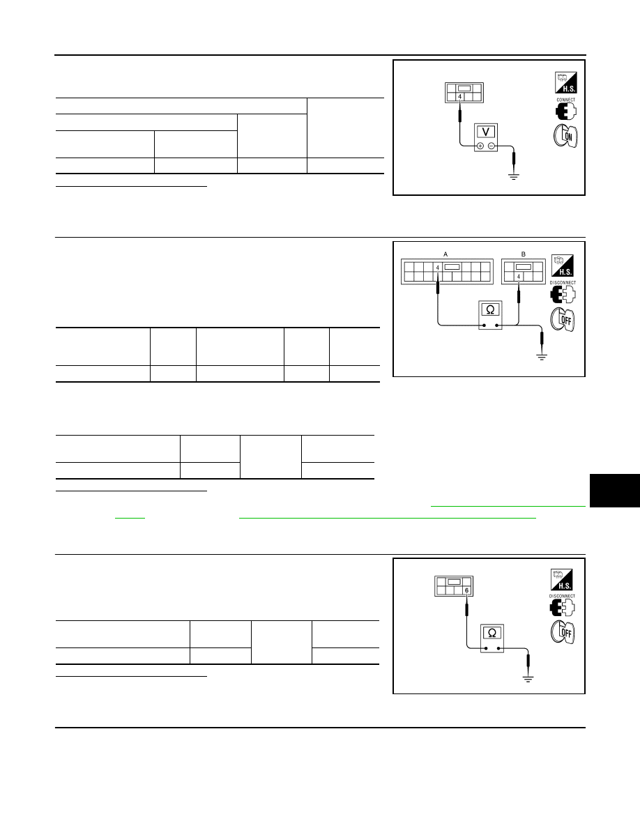
Check voltage between front power window motor RH connector

D104 terminal 4 and ground.

Is the inspection result normal?

YES

>> GO TO 4

NO

>> GO TO 3

3.

 CHECK HARNESS CONTINUITY 1

1. Turn ignition switch OFF.

2. Disconnect power window and door lock/unlock switch RH and

front power window motor RH connectors.

3. Check continuity between power window and door lock/unlock

switch RH connector D105 (A) terminal 4 and front power win-

dow motor RH connector D104 (B) terminal 4.

4. Check continuity between power window and door lock/unlock switch RH connector D105 (A) terminal 4

and ground.

Is the inspection result normal?

YES

>> Replace power window and door lock/unlock switch RH. Refer to 

PWC-108, "Removal and Instal-

lation"

. After that, refer to 

PWC-38, "PASSENGER SIDE : Special Repair Requirement"

.

NO

>> Repair or replace harness or connectors.

4.

 CHECK ENCODER GROUND CIRCUIT

1. Turn ignition switch OFF.

2. Disconnect front power window motor RH connector.

3. Check continuity between front power window motor RH con-

nector D104 terminal 6 and ground.

Is the inspection result normal?

YES

>> GO TO 6

NO

>> GO TO 5

5.

 CHECK HARNESS CONTINUITY 2

Terminal

Voltage (V)

(Approx.)

(+)

(–)

 Front power window 

motor RH connector

Terminal

D104

4

Ground

10

ALKIA0296ZZ

Power window and 

door lock/unlock 

switch RH connector

Terminal

Front power window 
motor RH connector

Terminal

Continuity

D105 (A)

4

D104 (B)

4

Yes

ALKIA0306ZZ

Power window and door lock/

unlock switch RH connector

Terminal

Ground

Continuity

D105 (A)

4

No

Front power window motor RH 

connector

Terminal

Ground

Continuity 

D104

6

Yes

ALKIA0298ZZ

PWC-38

< DTC/CIRCUIT DIAGNOSIS >

[LH&RH FRONT WINDOW ANTI-PINCH]

ENCODER

1. Disconnect power window and door lock/unlock switch RH con-

nector.

2. Check continuity between power window and door lock/unlock

switch RH connector D105 (A) terminal 3 and front power win-

dow motor RH connector D104 (B) terminal 6.

Is the inspection result normal?

YES

>> Replace power window and door lock/unlock switch RH. Refer to 

PWC-108, "Removal and Instal-

lation"

. After that, refer to 

PWC-38, "PASSENGER SIDE : Special Repair Requirement"

.

NO

>> Repair or replace harness or connectors.

6.

 CHECK HARNESS CONTINUITY 3

1. Disconnect power window and door lock/unlock switch RH con-

nector.

2. Check continuity between power window and door lock/unlock

switch RH connector D105 (A) terminals 12, 15 and front power

window motor RH connector D104 (B) terminals 3, 5.

3. Check continuity between power window and door lock/unlock switch RH connector D105 (A) terminals

12, 15 and ground.

Is the inspection result normal?

YES

>> Replace front power window motor RH. Refer to 

GW-18, "Removal and Installation"

. After that,

refer to 

PWC-38, "PASSENGER SIDE : Special Repair Requirement"

.

NO

>> Repair or replace harness or connectors.

PASSENGER SIDE : Special Repair Requirement

INFOID:0000000010051234

1.

 PERFORM INITIALIZATION PROCEDURE

Perform initialization procedure. Refer to 

PWC-7, "ADDITIONAL SERVICE WHEN REMOVING BATTERY

NEGATIVE TERMINAL : Special Repair Requirement"

 and 

PWC-7, "ADDITIONAL SERVICE WHEN

REPLACING CONTROL UNIT : Special Repair Requirement"

.

>> GO TO 2

2.

 CHECK ANTI-PINCH OPERATION

Check anti-pinch operation. Refer to 

PWC-7, "ADDITIONAL SERVICE WHEN REMOVING BATTERY NEGA-

TIVE TERMINAL : Special Repair Requirement"

 and 

PWC-7, "ADDITIONAL SERVICE WHEN REPLACING

CONTROL UNIT : Special Repair Requirement"

.

Power window and door 

lock/unlock switch RH 

connector

Terminal

Front power window 
motor RH connector

Terminal

Continuity

D105 (A)

3

D104 (B)

6

Yes

ALKIA0307ZZ

Power window and 

door lock/unlock 

switch RH connector

Terminal

Front power window 
motor RH connector

Terminal

Continuity

D105 (A)

12

D104 (B)

3

Yes

15

5

ALKIA0308ZZ

Power window and door 

lock/unlock switch RH con-

nector

Terminal

Ground

Continuity

D105 (A)

12

No

15

ENCODER

PWC-39

< DTC/CIRCUIT DIAGNOSIS >

[LH&RH FRONT WINDOW ANTI-PINCH]

C

D

E

F

G

H

I

J

L

M

A

B

PWC

N

O

P

>> End.

PWC-40

< DTC/CIRCUIT DIAGNOSIS >

[LH&RH FRONT WINDOW ANTI-PINCH]

DOOR SWITCH

DOOR SWITCH

Description

INFOID:0000000010051235

Detects front door open/close condition.

Component Function Check

INFOID:0000000010051236

1.

CHECK FUNCTION

 With CONSULT

Check front door switches DOOR SW-DR and DOOR SW-AS in Data Monitor mode with CONSULT.

Is the inspection result normal?

YES

>> Front door switches are OK.

NO

>> Refer to 

PWC-40, "Diagnosis Procedure"

.

Diagnosis Procedure

INFOID:0000000010051237

Regarding Wiring Diagram information, refer to 

PWC-83, "Wiring Diagram"

.

1.

CHECK FRONT DOOR SWITCH INPUT SIGNAL

1. Turn ignition switch OFF.

2. Check signal between BCM connector and ground with oscillo-

scope.

Monitor item

Condition

DOOR SW-DR

CLOSE 

→ OPEN: OFF → ON

DOOR SW-AS

AWKIA1419ZZ


Content   ..  933  934  935  936   ..