Nissan Sentra. Manual - part 316
DMS-36
< DTC/CIRCUIT DIAGNOSIS >
[ECO MODE (CVT)]
ECO MODE SWITCH
Is the inspection result normal?
YES
>> GO TO 13.
NO
>> GO TO 9.
9.
CHECK GROUND CIRCUIT
1. Turn ignition switch OFF.
2. Check the continuity between ECO mode switch harness connector and ground.
Is the inspection result normal?
YES
>> GO TO 10.
NO
>> Repair or replace damaged parts.
10.
CHECK CIRCUIT BETWEEN COMBINATION METER AND ECO MODE SWITCH (1)
1. Disconnect combination meter harness connector M24.
2. Check continuity between combination meter harness connector terminal and ECO mode switch harness
connector terminal.
Is the inspection result normal?
YES
>> GO TO 11.
NO
>> Repair or replace damaged parts.
11.
CHECK CIRCUIT BETWEEN COMBINATION METER AND ECO MODE SWITCH (2)
Check continuity between combination meter harness connector terminal and ECO mode switch harness con-
nector terminal.
Is the inspection result normal?
YES
>> GO TO 12.
NO
>> Repair or replace damaged parts.
12.
CHECK COMBINATION METER INPUT/OUTPUT SIGNAL
1. Connect all of disconnected connectors.
2. Check input/output signal of combination meter. Refer to
Is the inspection result normal?
YES
>> Check intermittent incident. Refer to
GI-39, "Intermittent Incident"
.
NO
>> Replace combination meter. Refer to
MWI-77, "Removal and Installation"
13.
CHECK ECO MODE SWITCH
Check ECO mode switch. Refer to
DMS-37, "Component Inspection"
.
Is the inspection result normal?
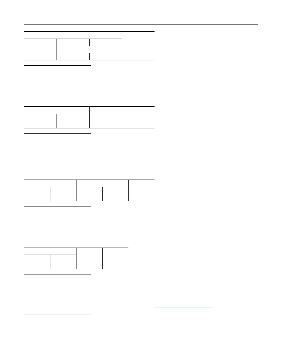
ECO mode switch
Voltage
(Approx.)
Connector
+
-
Terminal
M82
6
8
5 V
ECO mode switch
—
Continuity
Connector
Terminal
M82
8
Ground
Existed
Combination meter
ECO mode switch
Continuity
Connector
Terminal
Connector
Terminal
M24
25
M82
6
Existed
Combination meter
—
Continuity
Connector
Terminal
M24
25
Ground
Not existed