Nissan Sentra. Manual - part 139
BCS-126
< REMOVAL AND INSTALLATION >
[WITHOUT INTELLIGENT KEY SYSTEM]
BCM (BODY CONTROL MODULE)
REMOVAL AND INSTALLATION
BCM (BODY CONTROL MODULE)
Removal and Installation
INFOID:0000000009757400
NOTE:
Before replacing BCM, perform “READ CONFIGURATION” to save or print current vehicle specification. Refer
to
BCS-116, "CONFIGURATION (BCM) : Description"
.
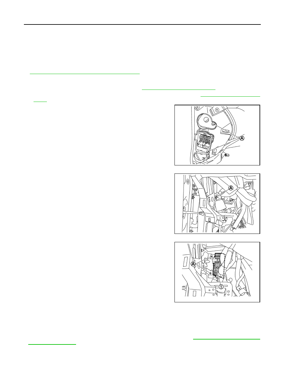
REMOVAL
1. Disconnect the negative battery terminal. Refer to
PG-52, "Removal and Installation"
2. Remove instrument lower panel LH and instrument side finisher LH. Refer to
.
3. Remove fuse block (J/B) screws (A) and position (BCM) aside.
4. Remove harness clip (A).
5. Remove the screws (A) from the BCM (1).
6. Disconnect the harness connectors and remove the BCM.
INSTALLATION
Installation is in the reverse order of removal.
CAUTION:
• Perform “CONFIGURATION (BCM)” when replacing BCM. Refer to
JMMIA1224ZZ
JMMIA1225ZZ
JMMIA1226ZZ