Nissan Sentra. Manual - part 138
BCS-122
< DTC/CIRCUIT DIAGNOSIS >
[WITHOUT INTELLIGENT KEY SYSTEM]
COMBINATION SWITCH INPUT CIRCUIT
Is the inspection result normal?
YES
>> Replace combination switch.
NO
>> Replace BCM. Refer to
BCS-126, "Removal and Installation"
.
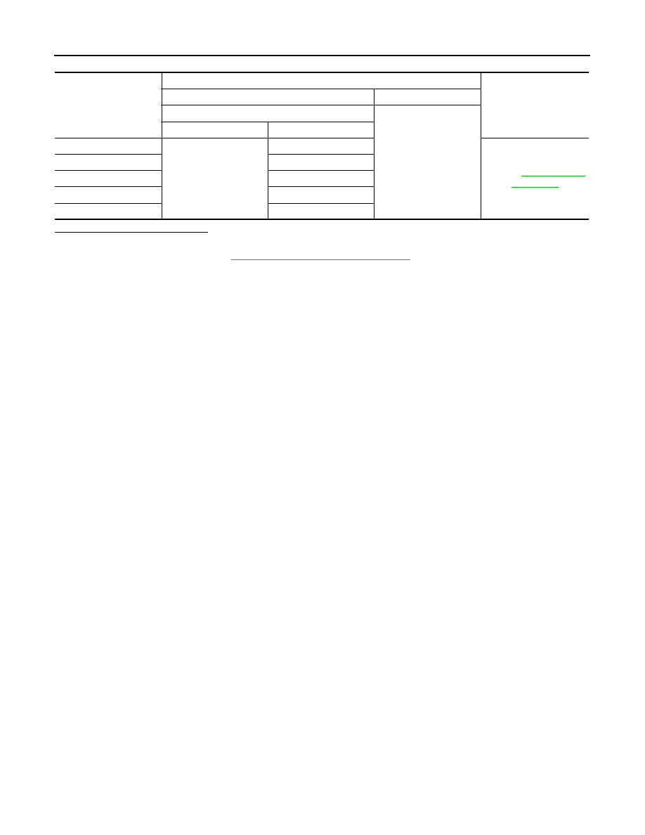
BCM signal
Terminals
Voltage
(+)
(
−)
BCM
Ground
Connector
Terminal
OUTPUT 1
M21
36
.
OUTPUT 2
35
OUTPUT 3
34
OUTPUT 4
33
OUTPUT 5
32