Nissan Leaf. Manual - part 964
MWI
COMBINATION METER
MWI-59
< ECU DIAGNOSIS INFORMATION >
C
D
E
F
G
H
I
J
K
L
M
B
A
O
P
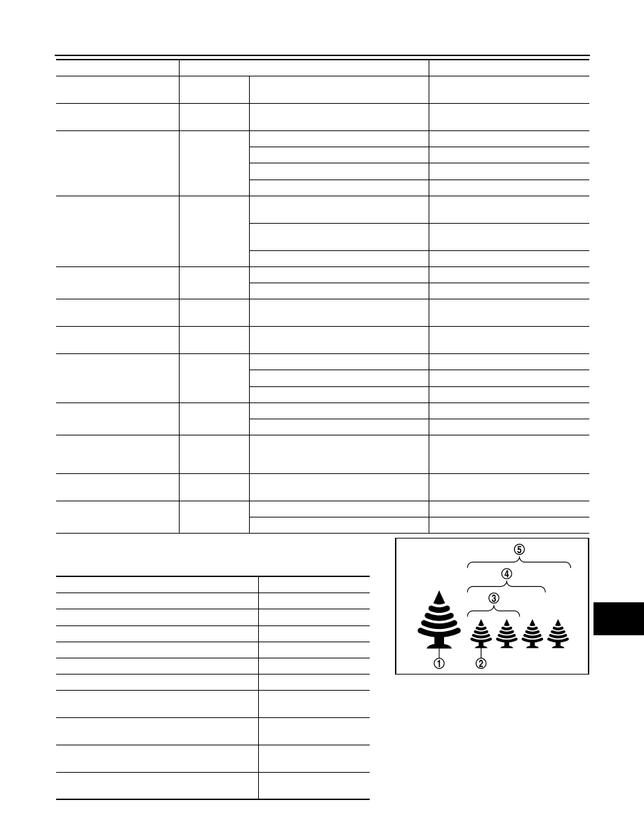
*: “ECO IND2” displays the items in the Status column of the follow-
ing table.
100V CHG TIME
Power switch
ON
—
Displays 100 V charging time.
200V CHG TIME
Power switch
ON
—
Displays 200 V charging time.
CHARGE STATE
Power switch
ON
100 V charging
100 V
200 V charging
200 V
In Quick Charging
QICK CHG
Other than the above
Off
DCDC W DSP
Power switch
ON
During DC/DC converter warning (“stop ve-
hicle”) indication
STOP
During DC/DC converter warning (“apply
parking brake”) indication
CRUISE
Other than the above
Off
SFT W/L
Power switch
ON
Electric shift warning lamp ON
On
Electric shift warning lamp OFF
Off
DTE DIF
[mi or km]
Power switch
ON
—
Input value of driving range difference
signal
DTE INPUT
[mi or km]
Power switch
ON
—
Input value of driving range signal
DTE 2ND W
Power switch
ON
Driving range display “– – –” display
On
Driving range display “– – –” blinking
BLINK
Other than the above
Off
BAT LOW W/L
Power switch
ON
Low battery charge warning lamp ON
On
Low battery charge warning lamp OFF
Off
ELE COMPR OFF
[mi or km]
Power switch
ON
—
Input value of A/C OFF average elec-
tricity consumption for driving range
signal
ELE COMPR ON
[mi or km]
Power switch
ON
—
Input value of A/C ON average electric-
ity consumption for driving range signal
DTE BLINK
Power switch
ON
Driving range display blinking
On
Other than the above
Off
Displays number of ON segments of ECO tree
Status
1 segment of ECO tree (1) illuminates
SEG11
2 segments of ECO tree (1) illuminate
SEG12
3 segments of ECO tree (1) illuminate
SEG13
4 segments of ECO tree (1) illuminate
SEG14
5 segments of ECO tree (1) illuminate
SEG15
ECO tree (2) illuminates
SEG21
• ECO tree (2) illuminates
• 1 segments of ECO tree (1) illuminate
SEG11+SEG21
• ECO tree (2) illuminates
• 2 segments of ECO tree (1) illuminate
SEG12+SEG21
• ECO tree (2) illuminates
• 3 segments of ECO tree (1) illuminate
SEG13+SEG21
• ECO tree (2) illuminates
• 4 segments of ECO tree (1) illuminate
SEG14+SEG21
Monitor item
Condition
Value/Status
JSNIA4440ZZ