Nissan Leaf. Manual - part 963
MWI
COMBINATION METER
MWI-55
< ECU DIAGNOSIS INFORMATION >
C
D
E
F
G
H
I
J
K
L
M
B
A
O
P
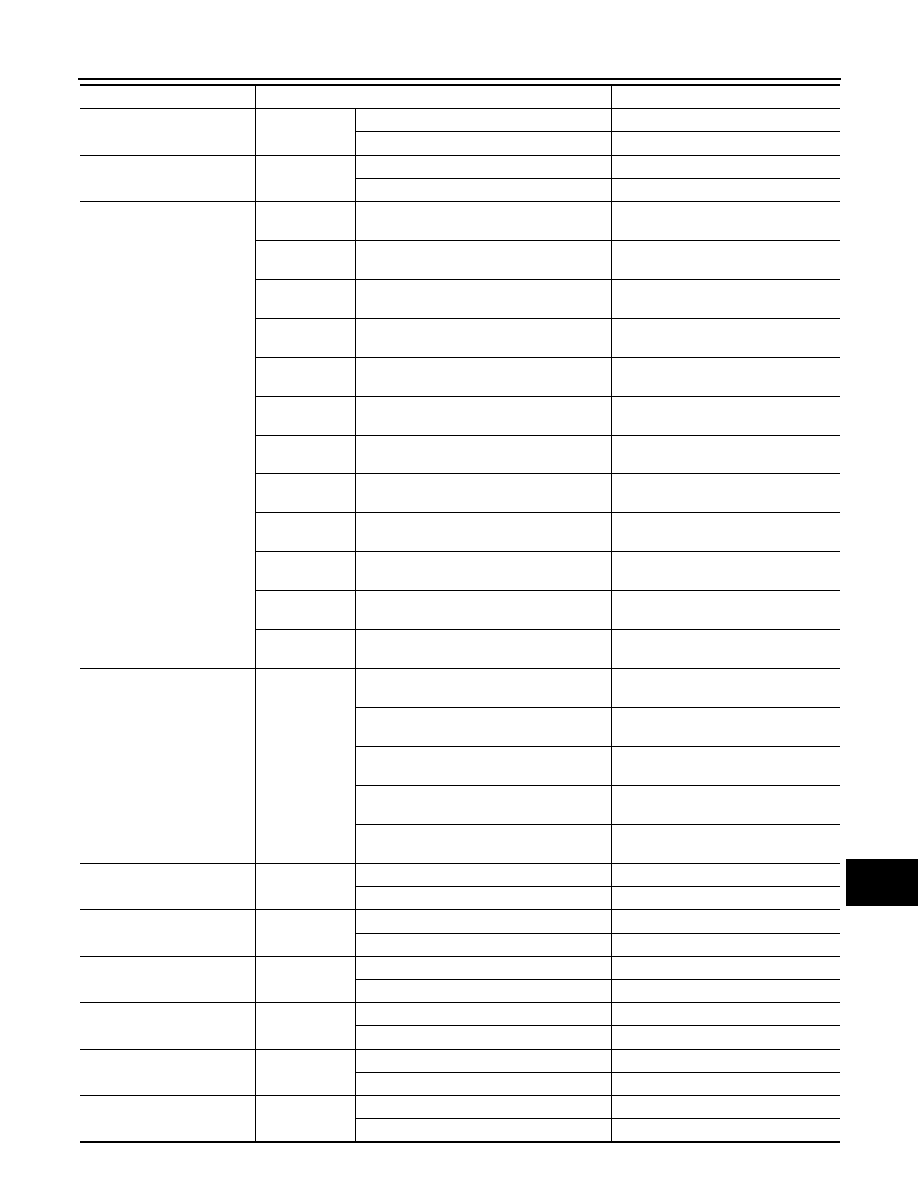
READY IND
Power switch
ON
READY to drive indicator lamp ON
On
READY to drive indicator lamp OFF
Off
CHAGE W/L
Power switch
ON
12V battery charge warning lamp ON
On
12V battery charge warning lamp OFF
Off
LCD
Power switch
ON
During engine start information indication
B&P I
Power switch
ACC
During engine start information indication
B&P N
Power switch
LOCK
During key ID warning indication
ID NG
Power switch
LOCK
During steering lock information indication
ROTAT
Power switch
LOCK
During P position warning indication
SFT P
Power switch
LOCK
During Intelligent Key insert information in-
dication
INSRT
Power switch
LOCK
During Intelligent Key low battery warning
indication
BATT
Power switch
ON
During take away warning indication
NO KY
Power switch
LOCK
During key warning indication
OUTKY
Power switch
ON
During ACC warning indication
LK WN
Power switch
LOCK
During key ID verification information indi-
cation
KY>PSW
Power switch
ON
Other than above
Off
SHIFT IND
Power switch
ON
During the indication of “P” by shift position
indicator
P
During the indication of “R” by shift position
indicator
R
During the indication of “N” by shift position
indicator
N
During the indication of “D” by shift position
indicator
D
During the indication of “B” by shift position
indicator
B
BUCKLE SW
Power switch
ON
Driver seat belt not fastened
On
Driver seat belt fastened
Off
BRAKE OIL SW
Power switch
ON
Brake fluid level switch ON
On
Brake fluid level switch OFF
Off
PASS BUCKLE SW
Power switch
ON
Passenger seat belt not fastened
On
Passenger seat belt fastened
Off
MODE A SW
Power switch
ON
When enter switch is pressed
On
Other than above
Off
MODE B SW
Power switch
ON
When select switch is pressed
On
Other than above
Off
LED LMP R OPEN
Power switch
ON
Front combination lamp RH malfunction
On
Front combination lamp RH normal
Off
Monitor item
Condition
Value/Status