Nissan Primera P11. Manual - part 248


  Index      Nissan     Nissan Primera P11 (2001 year) - Service and Repair Manual


Search            


Content   ..  246  247  248  249   ..


Nissan Primera P11. Manual - part 248


Diagnostic Procedure

NCEC0160

1

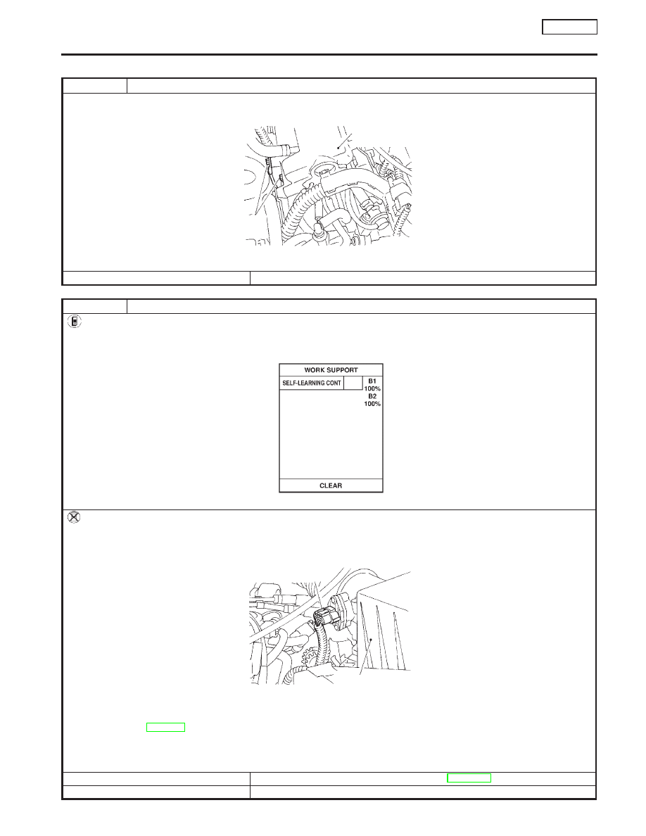
RETIGHTEN GROUND SCREWS

1. Turn ignition switch “OFF”.
2. Loosen and retighten engine ground screws.

SEF202X

©

GO TO 2.

2

CLEAR THE SELF-LEARNING DATA

With CONSULT-II

1. Start engine and warm it up to normal operating temperature.
2. Select “SELF-LEARN CONTROL” in “WORK SUPPORT” mode with CONSULT-II.
3. Clear the self-learning control coefficient by touching “CLEAR”.

SEF652Y

4. Run engine for at least 10 minutes at idle speed. Is the 1st trip DTC P0171 detected? Is it difficult to start engine?

Without CONSULT-II

1. Start engine and warm it up to normal operating temperature.
2. Turn ignition switch “OFF”.
3. Disconnect mass air flow sensor harness connector, and restart and run engine for at least 3 seconds at idle speed.

SEF203X

4. Stop engine and reconnect mass air flow sensor harness connector.
5. Make sure diagnostic trouble code No. 0100 is displayed in Diagnostic Test Mode II.
6. Erase the diagnostic test mode II (Self-diagnostic results) memory. Refer to “HOW TO ERASE EMISSION-RELATED DIAGNOSTIC

INFORMATION”, EC-SR-56.

7. Make sure diagnostic trouble code No. 0000 is displayed in Diagnostic Test Mode II.
8. Run engine for at least 10 minutes at idle speed. Is the 1st trip DTC 0171 detected? Is it difficult to start engine?

Yes or No

Yes

©

Perform trouble diagnosis for DTC P0171. Refer to EC-SR-212.

No

©

GO TO 3.

Intake manifold
collector

Engine
ground

Air cleaner

Mass air flow sensor
harness connector

DTC P0138 HEATED OXYGEN SENSOR 2

(REAR) (MAX. VOLTAGE MONITORING)

SR20DE

Diagnostic Procedure

EC-191

3

CHECK INPUT SIGNAL CIRCUIT

1. Disconnect heated oxygen sensor 2 (rear) harness connector and ECM harness connector.
2. Check harness continuity between ECM terminal 63 and heated oxygen sensor 2 (rear) harness connector terminal 2.

Refer to wiring diagram.

Continuity should exist.

3. Check harness continuity between ECM terminal 63 (or terminal 2) and ground.

Continuity should not exist.

4. Also check harness for short to ground and short to power.

OK or NG

OK

©

GO TO 5.

NG

©

GO TO 4.

4

DETECT MALFUNCTIONING PART

Check the harness for open or short between ECM and heated oxygen sensor 2 (rear).

©

Repair open circuit or short to ground or short to power in harness or connectors.

5

CHECK GROUND CIRCUIT

1. Check harness continuity between heated oxygen sensor 2 (rear) harness connector terminal 3 and engine ground.

Refer to wiring diagram.

Continuity should exist.

2. Also check harness for short to ground and short to power.

OK or NG

OK

©

GO TO 6.

NG

©

Repair open circuit or short to ground or short to power in harness or connectors.

6

CHECK HEATED OXYGEN SENSOR 2 (REAR)

Refer to “Component Inspection”, EC-SR-193.

OK or NG

OK

©

GO TO 7.

NG

©

Replace heated oxygen sensor 2 (rear).

7

CHECK INTERMITTENT INCIDENT

Perform “TROUBLE DIAGNOSIS FOR INTERMITTENT INCIDENT”, EC-SR-114.

©

INSPECTION END

DTC P0138 HEATED OXYGEN SENSOR 2

(REAR) (MAX. VOLTAGE MONITORING)

SR20DE

Diagnostic Procedure (Cont’d)

EC-192

Component Inspection

NCEC0161

HEATED OXYGEN SENSOR 2 (REAR)

NCEC0161S01

With CONSULT-II

1)

Start engine and drive vehicle at a speed of more than 70 km/h
(43 MPH) for 2 consecutive minutes..

2)

Stop vehicle with engine running.

3)

Select “FUEL INJECTION” in “ACTIVE TEST” mode, and
select “HO2S2 (B1)” as the monitor item with CONSULT-II.

4)

Check “HO2S2 (B1)” at idle speed when adjusting “FUEL
INJECTION” to ±25%.
“HO2S2 (B1)” should be above 0.48V at least once when
the “FUEL INJECTION” is +25%.
“HO2S2 (B1)” should be below 0.43V at least once when
the “FUEL INJECTION” is −25%.

CAUTION:

Discard any heated oxygen sensor which has been dropped
from a height of more than 0.5 m (19.7 in) onto a hard surface
such as a concrete floor; use a new one.

Without CONSULT-II

1)

Start engine and drive vehicle at a speed of 70 km/h (43 MPH)
for 2 consecutive minutes.

2)

Stop vehicle with engine running.

3)

Set voltmeter probes between ECM terminals 63 (Heated oxy-
gen sensor 2 (rear) signal) and engine ground.

4)

Check the voltage when revving up to 4,000 rpm under no load
at least 10 times.
(Depress and release accelerator pedal as soon as possible.)
The voltage should be above 0.48V at least once.
If the voltage is above 0.48V at step 4, step 5 is not nec-
essary.

5)

Check the voltage when revving up to 6,000 rpm under no
load. Or keep vehicle at idling for 10 minutes, then check the
voltage. Or check the voltage when coasting from 80 km/h (50
MPH) in 3rd gear position (M/T), D position with “SPORTS
MODE SW” OFF or without “MANUAL MODE” (CVT).
The voltage should be below 0.43V at least once.

CAUTION:

Discard any heated oxygen sensor which has been dropped
from a height of more than 0.5 m (19.7 in) onto a hard surface
such as a concrete floor; use a new one.

NEF091A

SEF989R

(Reference data)

The voltage should be above
0.48V at least one time.

The voltage should be below
0.43V at least one time.

x0.01V

SEF032X

DTC P0138 HEATED OXYGEN SENSOR 2

(REAR) (MAX. VOLTAGE MONITORING)

SR20DE

Component Inspection

EC-193

Component Description

NCEC0162

The heated oxygen sensor 2 (rear) (Rear HO2S), after three way
catalyst, monitors the oxygen level in the exhaust gas.
Even if switching characteristics of the heated oxygen sensor 1
(front) are shifted, the air fuel ratio is controlled to stoichiometric,
by the signal from the heated oxygen sensor 2 (rear).
This sensor is made of ceramic zirconia. The zirconia generates
voltage from approximately 1V in richer conditions to 0V in leaner
conditions.
Under normal conditions the heated oxygen sensor 2 (rear) is not
used for engine control operation.

CONSULT-II Reference Value in Data Monitor
Mode

NCEC0163

Specification data are reference values.

MONITOR ITEM

CONDITION

SPECIFICATION

HO2S2 (B1)

I

Engine: After warming up

Revving engine from idle to 3,000
rpm

0 - 0.3V

+,

Approx. 0.6 - 1.0V

HO2S2 MNTR
(B1)

LEAN

+,

RICH

ECM Terminals and Reference Value

NCEC0164

Specification data are reference values and are measured between each terminal and 48 (ECM ground).

TERMI-

NAL

NO.

WIRE

COLOR

ITEM

CONDITION

DATA (DC Voltage)

63

L

Heated oxygen sensor 2
(rear)

[Engine is running]

I

After warming up to normal operating temperature
and revving engine from idle to 2,000 rpm

0 - Approximately 1.0V

On Board Diagnosis Logic

NCEC0165

The heated oxygen sensor 2 (rear) has a much longer switching
time between rich and lean than the heated oxygen sensor 1
(front). The oxygen storage capacity before the three way catalyst
causes the longer switching time. To judge the malfunctions of
heated oxygen sensor 2 (rear), ECM monitors whether the switch-
ing response of the sensor’s voltage is faster than specified during
various driving conditions such as fuel-cut.

DTC No.

Malfunction is detected when ...

Check Items (Possible Cause)

P0139
0139

I

It takes more than the specified time for the sensor to
respond between rich and lean.

I

Harness or connectors
(The sensor circuit is open or shorted.)

I

Heated oxygen sensor 2 (rear)

I

Fuel pressure

I

Injectors

I

Intake air leaks

SEF327R

SEF302U

OK

NG

DTC P0139 HEATED OXYGEN SENSOR 2

(REAR) (RESPONSE MONITORING)

SR20DE

Component Description

EC-194


Content   ..  246  247  248  249   ..