Nissan Silvia. Manual - part 346
SBR686C
Precautions
PRECAUTIONS
NMSU0024
I
When installing each rubber part, final tightening must be
carried out under unladen condition* with tires on ground.
Oil will shorten the life of rubber bushes. Be sure to wipe
off any spilled oil.
*: Fuel, radiator coolant and engine oil full. Spare tire, jack,
hand tools and mats in designated positions.
I
Use flare nut wrench when removing or installing brake
tubes.
I
After installing removed suspension parts, check wheel
alignment.
I
Do not jack up at the trailing arm and lateral link.
I
Always torque brake lines when installing.
I
Lock nuts are unreusable parts; always use new ones.
When replacing, do not wipe the oil off of the new lock nut
before tightening.
Preparation
COMMERCIAL SERVICE TOOLS
NMSU0026
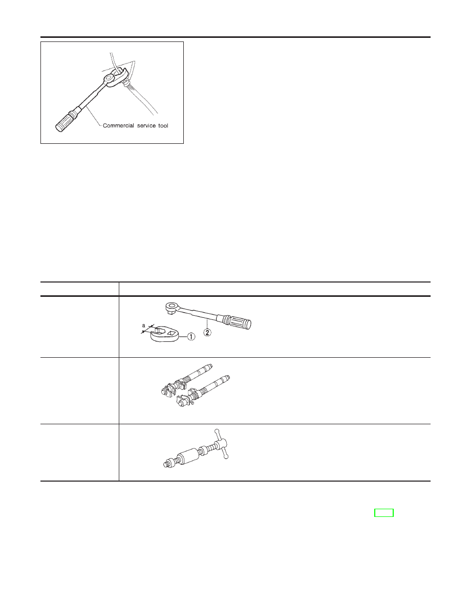
Tool name
Description
Equivalent to
GG94310000
1 Flare nut crowfoot
2 Torque wrench
NT360
Removing and installing brake piping
a: 10 mm (0.39 in)
Spring compressor
NT717
Removing and installing coil spring
Arm bushing remover
NT157
Removing and installing bushing of rear axle hous-
ing
Noise, Vibration and Harshness (NVH)
Troubleshooting
NMSU0027
Refer to “Noise, Vibration and Harshness (NVH) Troubleshooting”, “FRONT SUSPENSION”, SU-4.
REAR SUSPENSION
Precautions
SU-14