Nissan Silvia. Manual - part 345
SFA826A
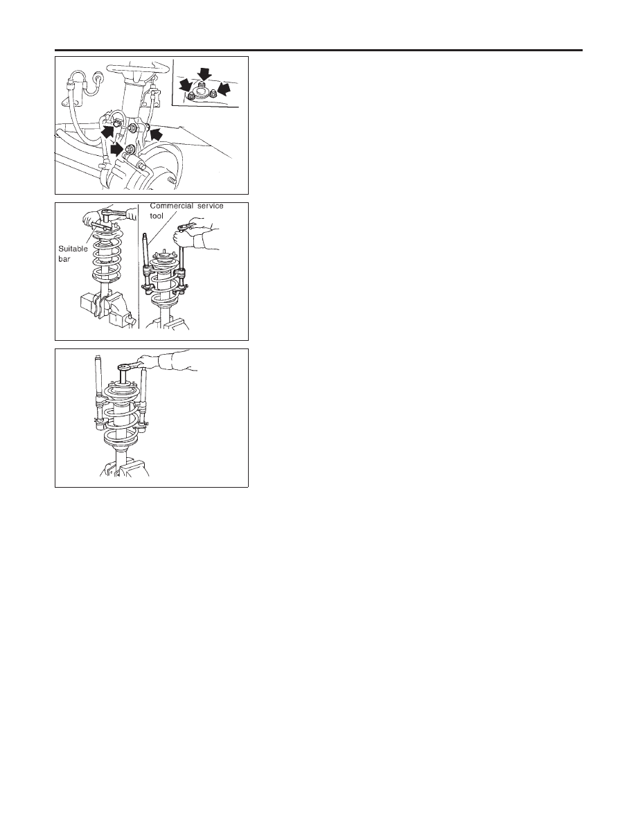
REMOVAL AND INSTALLATION
=NMSU0009
I
Remove shock absorber fixing bolt and nut (to hoodledge).
I
Do not remove piston rod lock nut on vehicle.
SSU002
DISASSEMBLY
NMSU0010
1.
Set shock absorber on vise, then loosen piston rod lock nut.
I
Do not remove piston rod lock nut at this time.
2.
Compress spring with Tool so that shock absorber mounting
insulator can be turned by hand.
WARNING:
Make sure that the pawls of the two spring compressors are
firmly hooked on the spring. The spring compressors must be
tightened alternately so as not to tilt the spring.
SSU003
3.
Remove piston rod lock nut.
INSPECTION
NMSU0011
Shock Absorber Assembly
NMSU0011S01
I
Check for smooth operation through a full stroke, both com-
pression and extension.
I
Check for oil leakage on welded or gland packing portions.
I
Check piston rod for cracks, deformation or other damage.
Replace if necessary.
Mounting Insulator and Rubber Parts
NMSU0011S02
I
Check cemented rubber-to-metal portion for separation or
cracks. Check rubber parts for deterioration.
Replace if necessary.
Thrust Bearing
NMSU0011S06
I
Check thrust bearing parts for abnormal noise or excessive
rattle in axial direction.
I
Replace if necessary.
Coil Spring
NMSU0011S03
I
Check for cracks, deformation or other damage. Replace if
necessary.
FRONT SUSPENSION
Coil Spring and Shock Absorber (Cont’d)
SU-10