Nissan Silvia. Manual - part 205
Trouble Diagnoses
NMEL0225
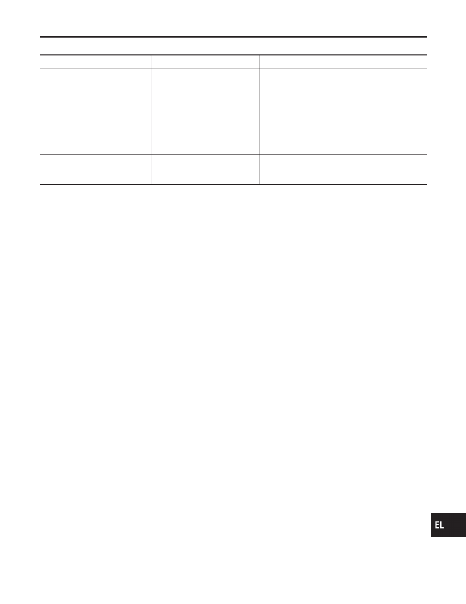
Symptom
Possible cause
Repair order
Power sunroof cannot be operated
using any switch.
1. 10A fuse, 30A fusible link and
M13 circuit breaker
2. Sunroof motor ground circuit
3. Sunroof switch
4. Sunroof switch circuit
5. Sunroof motor
1. Check 10A fuse [No. 5, located in fuse block (J/B)],
30A fusible link (letter I, located in fuse and fusible
link box) and M13 circuit breaker. Turn ignition
switch “ON” and verify battery positive voltage is
present at terminals 1 of sunroof motor.
2. Check sunroof motor ground circuit.
3. Check sunroof switch.
4. Check harness between sunroof switch and sunroof
motor.
5. Check sunroof motor.
Power sunroof cannot be operated
using one of the sunroof switches.
1. Sunroof switch
2. Sunroof switch circuit
1. Check sunroof switch.
2. Check the harness between sunroof motor and sun-
roof switch.
GI
MA
EM
LC
EC
FE
CL
MT
AT
PD
AX
SU
BR
ST
RS
BT
HA
SC
IDX
POWER SUNROOF
Trouble Diagnoses
EL-109