Nissan Silvia. Manual - part 197
CEL315A
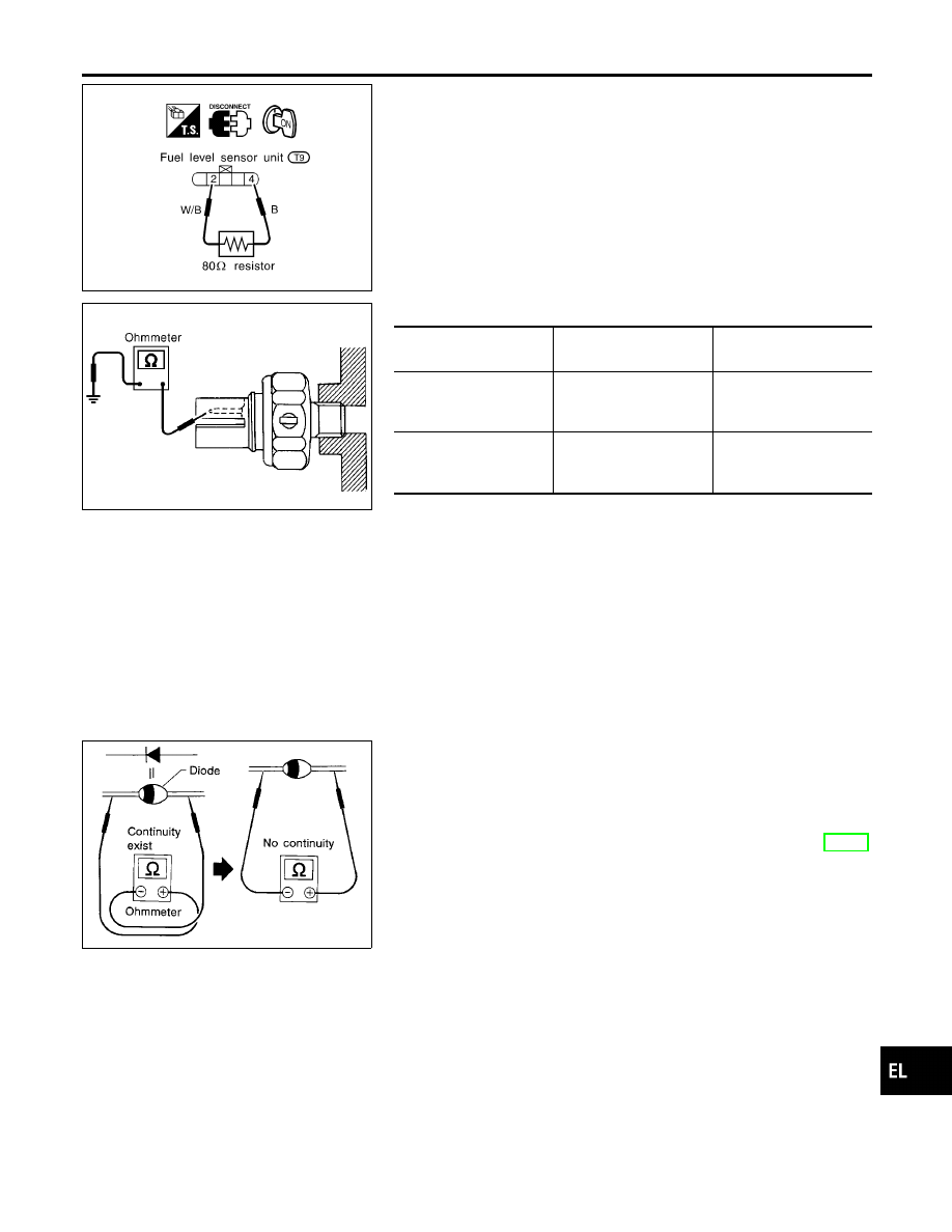
Electrical Components Inspection
NMEL0051
FUEL WARNING LAMP OPERATION CHECK
NMEL0051S01
1.
Turn ignition switch “OFF”.
2.
Disconnect fuel level sensor unit harness connector T9.
3.
Connect a resistor (80
Ω
) between fuel level sensor unit har-
ness connector terminals 2 and 4.
4.
Turn ignition switch “ON”.
The fuel warning lamp should come on.
MEL425F
OIL PRESSURE SWITCH CHECK
NMEL0051S02
Oil pressure
kPa (bar, kg/cm
2
, psi)
Continuity
Engine running
More than 10 - 20
(0.10 - 0.20, 0.1 - 0.2,
1 - 3)
No
Engine not running
Less than 10 - 20
(0.10 - 0.20, 0.1 - 0.2,
1 - 3)
Yes
Check the continuity between the terminals of oil pressure switch
and body ground.
SEL901F
DIODE CHECK
NMEL0051S03
I
Check continuity using an ohmmeter.
I
Diode is functioning properly if test results are as shown in the
figure at left.
I
Check diodes at the combination meter harness connector
instead of on the combination meter assembly. Refer to EL-74,
“WARNING LAMP” wiring diagrams.
NOTE:
Specification may vary depending on the type of tester. Before
performing this inspection, be sure to refer to the instruction
manual for the tester to be used.
GI
MA
EM
LC
EC
FE
CL
MT
AT
PD
AX
SU
BR
ST
RS
BT
HA
SC
IDX
WARNING LAMPS
Electrical Components Inspection
EL-77