Nissan Silvia. Manual - part 158
NOTE:
Voltage measurement must be made with throttle position
sensor installed in vehicle.
Throttle valve conditions
Voltage (V)
Completely closed
0.15 - 0.85 (a)
Partially open
Between (a) and (b)
Completely open
3.5 - 4.7 (b)
If NG, adjust closed throttle position switch. Refer to “Basic
Inspection”, EC-50.
6)
If it is impossible to adjust closed throttle position switch in
“Basic Inspection”, replace throttle position sensor.
SEC414C
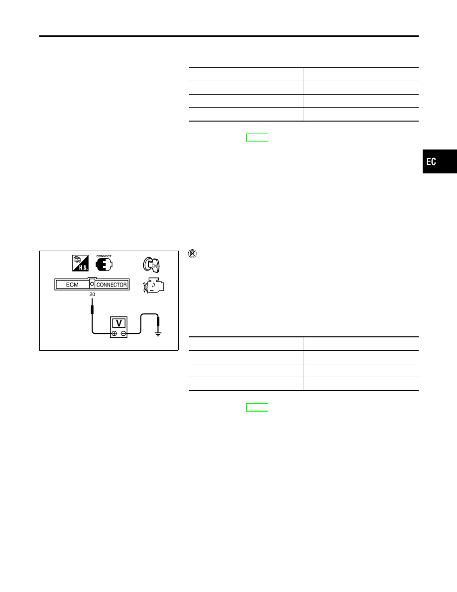
Without CONSULT-II
1)
Start engine and warm it up to normal operating temperature.
2)
Stop engine (ignition switch OFF).
3)
Turn ignition switch ON.
4)
Check voltage between ECM terminal 20 (Throttle position
sensor signal) and ground under the following conditions.
NOTE:
Voltage measurement must be made with throttle position
sensor installed in vehicle.
Throttle valve conditions
Voltage (V)
Completely closed
0.15 - 0.85 (a)
Partially open
Between (a) and (b)
Completely open
3.5 - 4.7 (b)
If NG, adjust closed throttle position switch. Refer to “Basic
Inspection”, EC-50.
5)
If it is impossible to adjust closed throttle position switch in
“Basic Inspection”, replace throttle position sensor.
GI
MA
EM
LC
FE
CL
MT
AT
PD
AX
SU
BR
ST
RS
BT
HA
SC
EL
IDX
DTC 0403 THROTTLE POSITION SENSOR
Component Inspection (Cont’d)
EC-147