Nissan Silvia. Manual - part 142
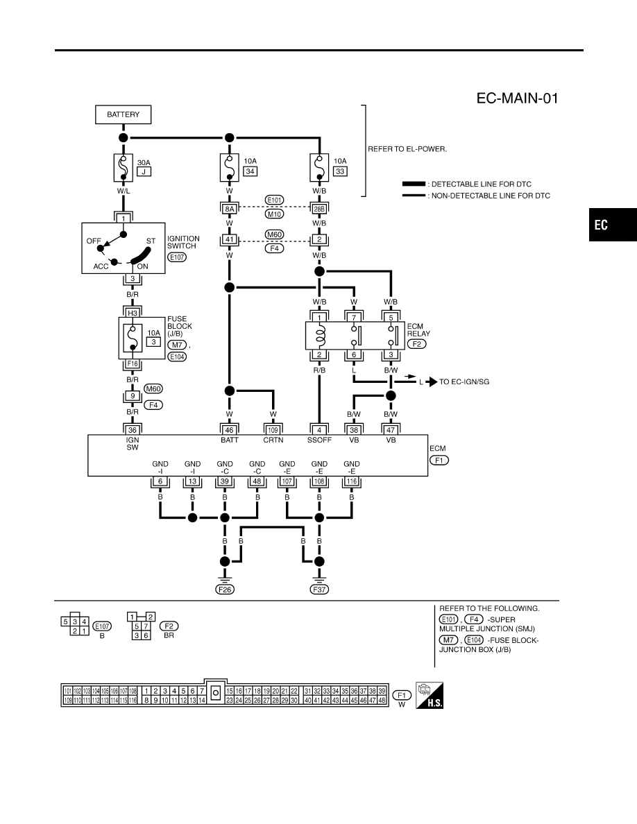
Main Power Supply and Ground Circuit
WIRING DIAGRAM
NMEC0661
TEC798
GI
MA
EM
LC
FE
CL
MT
AT
PD
AX
SU
BR
ST
RS
BT
HA
SC
EL
IDX
TROUBLE DIAGNOSIS FOR POWER SUPPLY
Main Power Supply and Ground Circuit
EC-83
|
|
|
Main Power Supply and Ground Circuit WIRING DIAGRAM NMEC0661 TEC798 GI MA EM LC FE CL MT AT PD AX SU BR ST RS BT HA SC EL IDX TROUBLE DIAGNOSIS FOR POWER SUPPLY Main Power Supply and Ground Circuit EC-83 |