Nissan Silvia. Manual - part 127
SEF312N
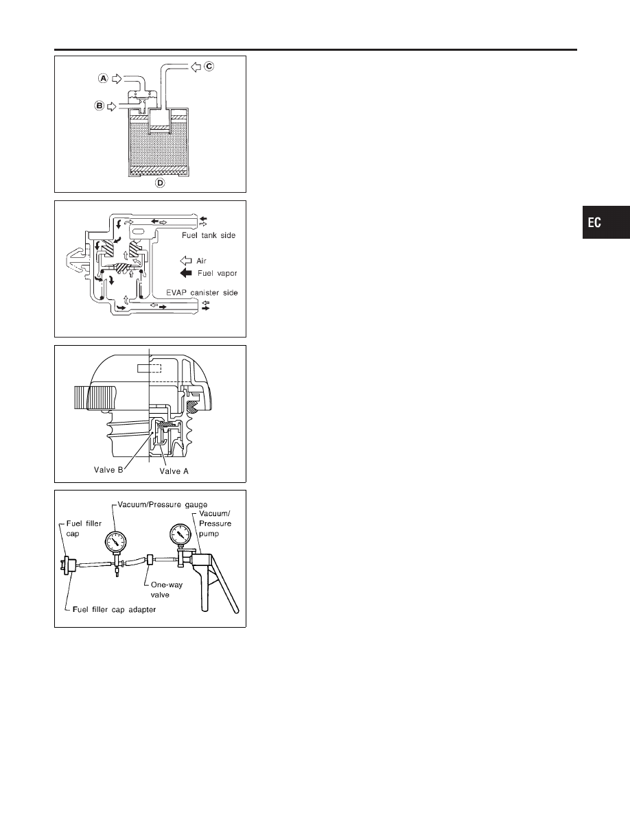
INSPECTION
NMEC0019
EVAP Canister
NMEC0019S01
Check EVAP canister as follows:
1.
Blow air through port A orally. Make sure that there is no leak-
age.
2.
Apply vacuum to port A. Block port D. Blow air through port C
orally. Check that air flows freely through port B.
MEC744B
Fuel Check Valve
NMEC0019S11
1.
Blow air through connector on fuel tank side.
A considerable resistance should be felt and a portion of air
flow should be directed toward the EVAP canister side.
2.
Blow air through connector on EVAP canister side.
Air flow should be smoothly directed toward fuel tank side.
3.
If fuel check valve is suspected of not properly functioning in
steps 1 and 2 above, replace it.
SEF989X
SEF943S
Fuel Tank Vacuum Relief Valve (Built into fuel filler cap)
NMEC0019S03
1.
Wipe clean valve housing.
2.
Check valve opening pressure and vacuum.
Pressure:
15.3 - 20.0 kPa (0.156 - 0.204 kg/cm
2
, 2.22 - 2.90 psi)
Vacuum:
−6.0 to −3.4 kPa (−0.061 to −0.035 kg/cm
2
, −0.87 to
−0.50 psi)
3.
If out of specification, replace fuel filler cap as an assembly.
CAUTION:
Use only a genuine fuel filler cap as a replacement.
GI
MA
EM
LC
FE
CL
MT
AT
PD
AX
SU
BR
ST
RS
BT
HA
SC
EL
IDX
ENGINE AND EMISSION BASIC CONTROL SYSTEM DESCRIPTION
Evaporative Emission System (Cont’d)
EC-23