Nissan Silvia. Manual - part 125
System Diagram
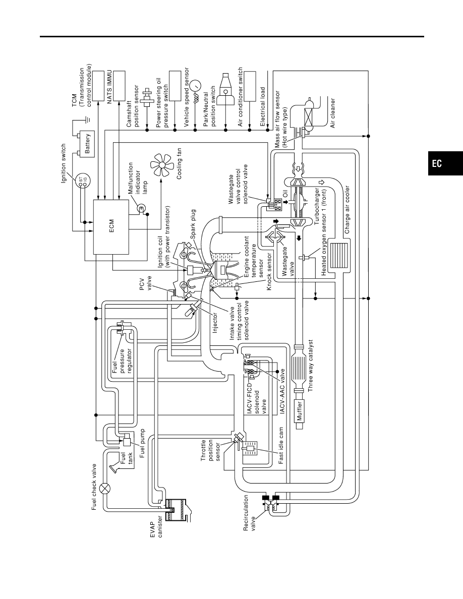
NMEC0011
SEC320C
GI
MA
EM
LC
FE
CL
MT
AT
PD
AX
SU
BR
ST
RS
BT
HA
SC
EL
IDX
ENGINE AND EMISSION CONTROL OVERALL SYSTEM
System Diagram
EC-15
|
|
|
System Diagram NMEC0011 SEC320C GI MA EM LC FE CL MT AT PD AX SU BR ST RS BT HA SC EL IDX ENGINE AND EMISSION CONTROL OVERALL SYSTEM System Diagram EC-15 |