Nissan Silvia. Manual - part 123


  Index      Nissan     Nissan Silvia - Service Manual (2001 year)


Search            


Content   ..  121  122  123  124   ..


Nissan Silvia. Manual - part 123


SEF706Y

Engine Fuel & Emission Control System

=NMEC0659

I

Always use a 12 volt battery as power source.

I

Do not attempt to disconnect battery cables while engine
is running.

I

Before connecting or disconnecting the ECM harness
connector, turn ignition switch OFF and disconnect nega-
tive battery terminal. Failure to do so may damage the
ECM because battery voltage is applied to ECM even if
ignition switch is turned off.

SEF707Y

I

Do not disassemble ECM.

I

If a battery terminal is disconnected, the memory will
return to the ECM value.
The ECM will now start to self-control at its initial value.
Engine operation can vary slightly when the terminal is
disconnected. However, this is not an indication of a prob-
lem. Do not replace parts because of a slight variation.

SEF308Q

I

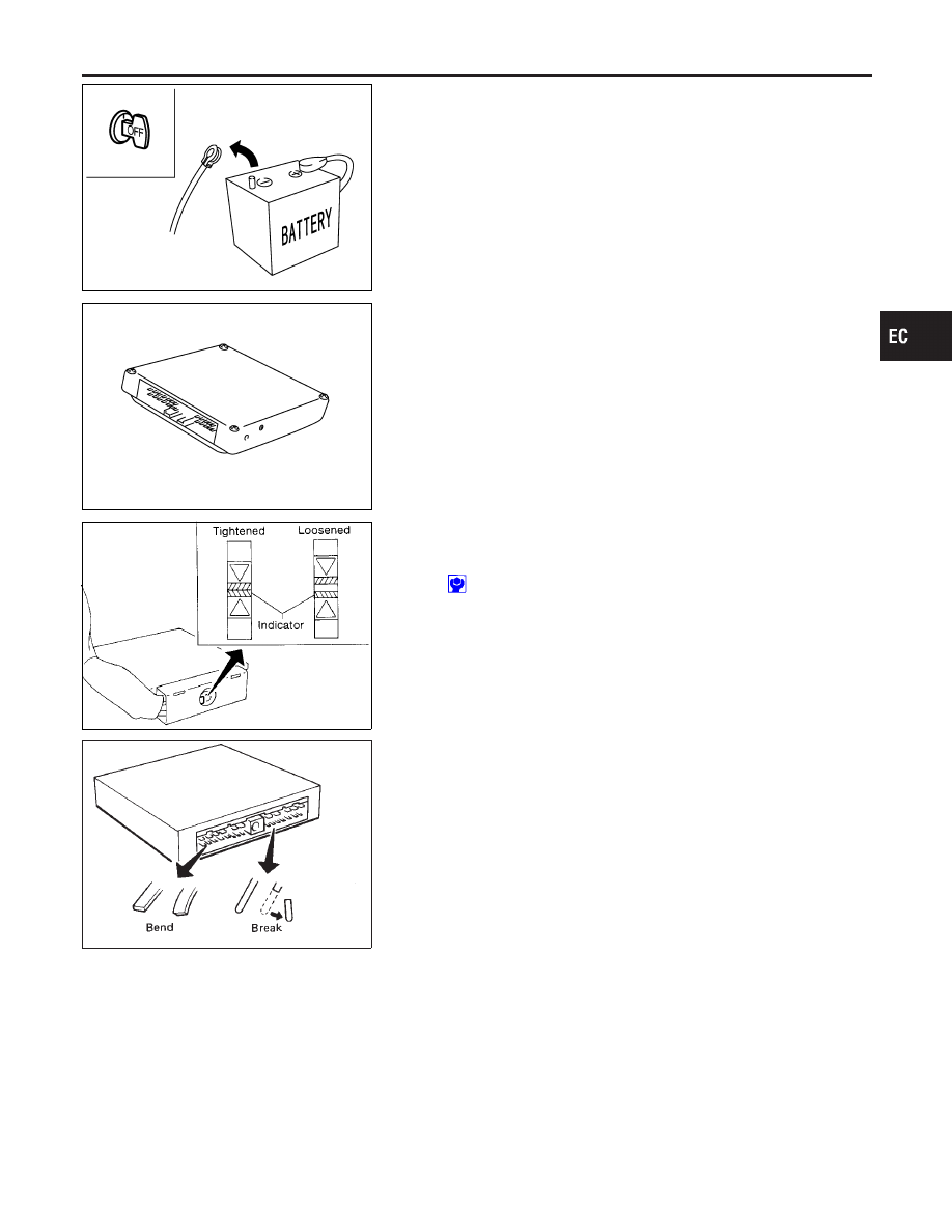
When connecting ECM harness connector, tighten secur-
ing bolt until the gap between orange indicators disap-
pears.

: 3.0 - 4.9 N·m (0.3 - 0.5 kg-m, 26 - 43 in-lb)

SEF291H

I

When connecting or disconnecting pin connectors into or
from ECM, take care not to damage pin terminals (bend or
break).
Make sure that there are not any bends or breaks on ECM
pin terminals when connecting pin connectors.

I

Securely connect ECM harness connectors.
A Poor connection can cause an extremely high (surge)
voltage to develop in coil and condenser, thus resulting in
damage to ICs.

I

Keep ECM harness at least 10 cm (4 in) away from adja-
cent harness, to prevent an ECM system malfunctions due
to receiving external noise, degraded operation of ICs, etc.

I

Keep ECM parts and harness dry.

GI

MA

EM

LC

FE

CL

MT

AT

PD

AX

SU

BR

ST

RS

BT

HA

SC

EL

IDX

PRECAUTIONS

Engine Fuel & Emission Control System

EC-7

MEF040D

I

Handle mass air flow sensor carefully to avoid damage.

I

Do not disassemble mass air flow sensor.

I

Do not clean mass air flow sensor with any type of deter-
gent.

I

Do not disassemble IAC valve-AAC valve.

I

Even a slight leak in the air intake system can cause seri-
ous problems.

I

Do not shock or jar the camshaft position sensor and
crankshaft position sensor.

I

Before replacing ECM, perform refer to “ECM Terminals
and Reference Value” inspection and make sure ECM
functions properly, EC-76.

SAT652J

I

After performing each TROUBLE DIAGNOSIS, perform
“DTC Confirmation Procedure” or “Overall Function
Check”.
The DTC should not be displayed in the “DTC Confirma-
tion Procedure” if the repair is completed. The “Overall
Function Check” should be a good result if the repair is
completed.

SEF348N

I

When measuring ECM signals with a circuit tester, never
allow the two tester probes to contact.
Accidental contact of probes will cause a short circuit and
damage the ECM power transistor.

I

Do not use ECM ground terminals when measuring input/
output voltage. Doing so may result in damage to the
ECM’s transistor. Use a ground other than ECM terminals,
such as the ground.

PRECAUTIONS

Engine Fuel & Emission Control System (Cont’d)

EC-8

SEF476P

I

Do not operate fuel pump when there is no fuel in lines.

I

Tighten fuel hose clamps to the specified torque.

SEF709Y

I

Do not depress accelerator pedal when starting.

I

Immediately after starting, do not rev up engine unneces-
sarily.

I

Do not rev up engine just prior to shutdown.

SEF708Y

I

When installing C.B. ham radio or a mobile phone, be sure
to observe the following as it may adversely affect elec-
tronic control systems depending on installation location.

1)

Keep the antenna as far as possible from the electronic
control units.

2)

Keep the antenna feeder line more than 20 cm (8 in) away
from the harness of electronic controls.
Do not let them run parallel for a long distance.

3)

Adjust the antenna and feeder line so that the standing-
wave ratio can be kept smaller.

4)

Be sure to ground the radio to vehicle body.

Wiring Diagrams and Trouble Diagnosis

NMEC0660

When you read Wiring diagrams, refer to the following:

I

GI-11, “HOW TO READ WIRING DIAGRAMS”

I

EL-7, “POWER SUPPLY ROUTING” for power distribution cir-
cuit

When you perform trouble diagnosis, refer to the following:

I

GI-31, “HOW TO FOLLOW TEST GROUPS IN TROUBLE
DIAGNOSES”

I

GI-20, “HOW TO PERFORM EFFICIENT DIAGNOSIS FOR AN
ELECTRICAL INCIDENT”

GI

MA

EM

LC

FE

CL

MT

AT

PD

AX

SU

BR

ST

RS

BT

HA

SC

EL

IDX

PRECAUTIONS

Engine Fuel & Emission Control System (Cont’d)

EC-9

Special Service Tools

NMEC0007

Tool number
Tool name

Description

KV10117100
Heated oxygen sensor
wrench

NT379

Loosening or tightening heated oxygen sensor with
22 mm (0.87 in) hexagon nut

Commercial Service Tools

NMEC0008

Tool name

Description

Fuel filler cap adapter

NT653

Checking fuel tank vacuum relief valve opening
pressure

Oxygen sensor thread
cleaner

NT778

Reconditioning the exhaust system threads before
installing a new oxygen sensor. Use with anti-seize
lubricant shown below.
a: 18 mm dia. with pitch 1.5 mm for Zirconia
Oxygen Sensor
b: 12 mm dia. with pitch 1.25 mm for Titania
Oxygen Sensor

Anti-seize lubricant
(Permatex

TM

133AR or

equivalent meeting MIL
specification MIL-A-907)

NT779

Lubricating oxygen sensor thread cleaning tool
when reconditioning exhaust system threads.

PREPARATION

Special Service Tools

EC-10


Content   ..  121  122  123  124   ..