Nissan Silvia. Manual - part 107
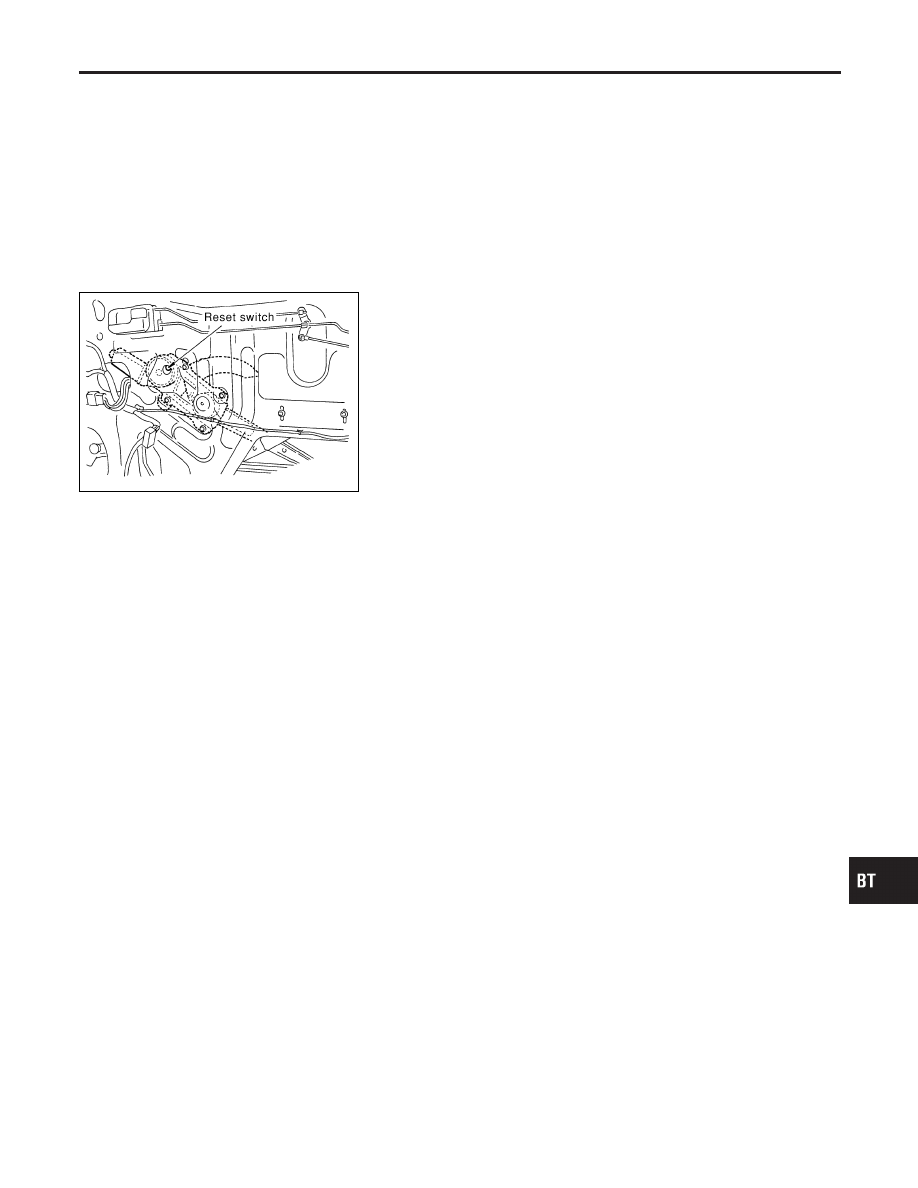
Door Limit Switch Reset (Driver side only)
=NMBT0008
RESET CONDITIONS
NMBT0008S01
After each of the following operations are performed, reset the limit
switch (with built-in motor).
I
Regulator removal and installation
I
Removal of motor from regulator
I
Operation of regulator as a single unit
I
Door glass removal and installation
I
Glass run removal and installation
I
Fitting adjustment
JBT127A
RESET PROCEDURES
NMBT0008S02
After installing parts, proceed as follows:
1.
Close the door window completely.
2.
Press the reset switch and open the door window completely.
3.
Release the reset switch. After making sure the reset switch
has returned to the original position, close the door window
completely.
4.
The limit switch is now reset.
CAUTION:
Be sure to manually open or close the door window. (Do not
use the automatic open-close procedures.)
GI
MA
EM
LC
EC
FE
CL
MT
AT
PD
AX
SU
BR
ST
RS
HA
SC
EL
IDX
DOOR
Door Limit Switch Reset (Driver side only)
BT-19