Nissan Silvia. Manual - part 100


  Index      Nissan     Nissan Silvia - Service Manual (2001 year)


Search            


Content   ..  98  99  100  101   ..


Nissan Silvia. Manual - part 100


6

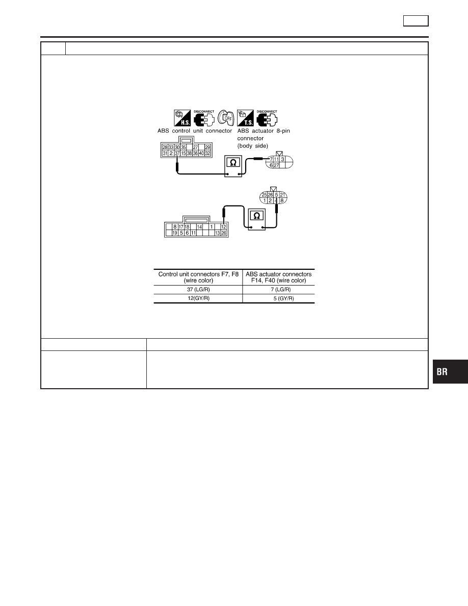
SOLENOID VALVE RELAY COIL POWER SUPPLY CHECK

1. Turn ignition switch “OFF”. Disconnect ABS actuator 8-pin connector.
2. Check continuity between ABS control unit connector (body side) terminal and ABS actuator 8-pin connector (body

side) terminal.

SBR829E

MTBL0646

Continuity should exist.

OK or NG

OK

©

GO TO 6.

NG

©

Check the following.

I

Harness connectors F14, F40, F7, F8

I

Harness for open or short between ABS actuator connector and control unit

If NG, repair harness or connectors.

GI

MA

EM

LC

EC

FE

CL

MT

AT

PD

AX

SU

ST

RS

BT

HA

SC

EL

IDX

TROUBLE DIAGNOSES FOR SYMPTOMS

ABS

7. Warning Lamp Stays On When Ignition Switch Is Turned On (Cont’d)

BR-83

7

CIRCUIT CHECK

1. Disconnect ABS actuator connector.
2. Connect continuity between ABS actuator connectors F14, F40 (actuator side) terminals 5 and 7.

SBR830E

Continuity should exist.

OK or NG

OK

©

GO TO 8.

NG

©

Replace ABS actuator.

8

SOLENOID VALVE RELAY CHECK

Go to “8 ABS ACTUATOR SOLENOID VALVE RELAY CHECK” in “Warning Lamp Does Not Come On When Ignition
Switch Is Turned ON”, BR-77.

OK

©

GO TO 9.

NG

©

Replace ABS actuator.

9

GROUND-SHORT CHECK FOR WARNING LAMP CIRCUIT

1. Turn ignition switch “OFF”.
2. Disconnect connectors from ABS control unit and ABS actuator 8-pin connector.
3. Check continuity between ABS control unit connector F8 (body side) terminal 33 (L/R) and ground.

SBR831E

Continuity should not exist.

OK or NG

OK

©

GO TO 10.

NG

©

Check the following.

I

Harness connector F8

I

Harness for open or short between control unit and fuse

If NG, repair harness or connector.

TROUBLE DIAGNOSES FOR SYMPTOMS

ABS

7. Warning Lamp Stays On When Ignition Switch Is Turned On (Cont’d)

BR-84

10

GROUND-SHORT CHECK FOR WARNING LAMP CIRCUIT

1. Disconnect ABS actuator ground terminal and ABS 8-pin connector.
2. Check continuity between ABS actuator 8-pin connector (actuator side) F14 terminal 11 (–) and ground.

NOTE:
Pay attention to tester polarity.
Specifications may vary depending on the type of tester.
Before performing this inspection, refer to the instruction manual of the tester.

SBR832E

Continuity should not exist.

OK or NG

OK

©

GO TO 11.

NG

©

Replace ABS actuator.

11

SOLENOID VALVE CIRCUIT

1. Disconnect ABS 8-pin connector.
2. Check continuity between ABS actuator 8-pin connectors (actuator side) F14, F40 terminals 3, 27, 1, 2, 25, 26 and

ground.

SBR833E

Continuity should not exist.

OK or NG

OK

©

Check control unit pin terminals for damage or the connection of ABS control unit har-
ness connector.
Reconnect control unit harness connector.
Then retest.

NG

©

Replace ABS actuator.

12

FUSE CHECK

Replace fuse.

Does the fuse blow out when ignition switch is turned “ON”?

Yes

©

GO TO 13.

No

©

INSPECTION END

GI

MA

EM

LC

EC

FE

CL

MT

AT

PD

AX

SU

ST

RS

BT

HA

SC

EL

IDX

TROUBLE DIAGNOSES FOR SYMPTOMS

ABS

7. Warning Lamp Stays On When Ignition Switch Is Turned On (Cont’d)

BR-85

13

CONTROL UNIT POWER SUPPLY CIRCUIT

1. Disconnect ABS control unit connector.
2. Check continuity between ABS control unit connector F7 (body side) terminal 12 (GY/R) and ground.

SBR834E

Continuity should not exist.

OK or NG

OK

©

Check control unit pin terminals for damage or the connection of ABS control unit har-
ness connector.
Reconnect control unit harness connector.
Then retest.

NG

©

Check the following.

I

Harness connector F7

I

Harness for open or short between control unit and fuse

If NG, repair harness or connector.

TROUBLE DIAGNOSES FOR SYMPTOMS

ABS

7. Warning Lamp Stays On When Ignition Switch Is Turned On (Cont’d)

BR-86


Content   ..  98  99  100  101   ..