Nissan Silvia. Manual - part 22
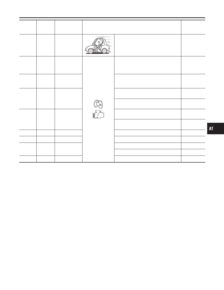
Terminal
No.
Wire color
Item
Condition
Judgement
standard
(Approx.)
40
W/PU
Vehicle speed
sensor
When moving vehicle at 2 to 3 km/h (1 to 2
MPH) for 1 m (3 ft) or more.
Voltage varies
between less
than 1.0V and
more than
4.5V.
41
R/Y
Throttle position
sensor
When depressing accelerator pedal slowly
after warming up engine.
(Voltage rises gradually in response to throttle
position.)
Fully-closed
throttle: 0.5V
Fully-open
throttle: 4V
42
GY
Throttle position
sensor
(Ground)
—
0V
43
G/Y
A/T mode switch
“POWER“
When setting A/T mode switch in “POWER”
position.
Battery volt-
age
When setting A/T mode switch in other posi-
tion.
0V
44
L/B
A/T mode switch
“SNOW”
When setting A/T mode swtich in “SNOW”
position.
Battery volt-
age
When setting A/T mode switch in other posi-
tion.
0V
45
—
—
—
—
46
—
—
—
—
47
W/R
A/T fluid tempera-
ture sensor
When ATF temperature is 20°C (68°F).
1.5V
When ATF temperature is 80°C (176°F).
0.5V
48
B
Ground
—
0V
*1: These terminals are connected to the ECM.
*2: These terminals are connected to the Data link connector.
GI
MA
EM
LC
EC
FE
CL
MT
PD
AX
SU
BR
ST
RS
BT
HA
SC
EL
IDX
TROUBLE DIAGNOSIS — GENERAL DESCRIPTION
TCM Terminals and Reference Value (Cont’d)
AT-85