Nissan Silvia. Manual - part 6
“D
3
” Position
=NMAT0012S0404
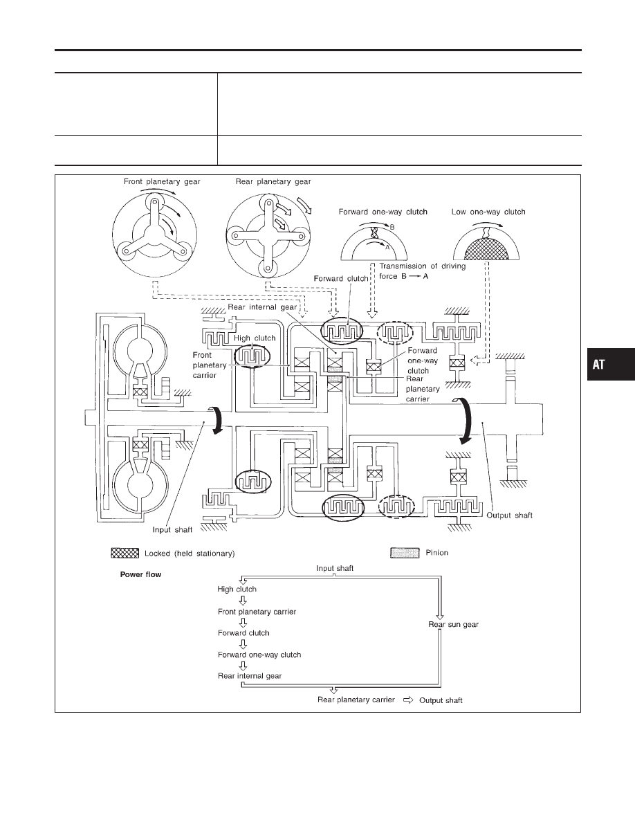
High clutch
Forward clutch
Forward one-way clutch
Input power is transmitted to front planetary carrier through high clutch. And front plan-
etary carrier is connected to rear internal gear by operation of forward clutch and forward
one-way clutch.
This rear internal gear rotation and another input (the rear sun gear) accompany rear
planetary carrier to turn at the same speed.
Overrun clutch
engagement conditions
D
3
: Overdrive control switch in “OFF”
Throttle opening less than 3/16
SAT098J
GI
MA
EM
LC
EC
FE
CL
MT
PD
AX
SU
BR
ST
RS
BT
HA
SC
EL
IDX
OVERALL SYSTEM
Shift Mechanism (Cont’d)
AT-21